Engine driven power inverter system with cogeneration

a technology of inverter and engine, which is applied in the direction of electric generator control, motor/generator/converter stopper, dynamo-electric converter control, etc., can solve the problems of virtually unworkable engines, reduce the amount of additional power drawn, reduce the rotational speed, and reduce the amount of additional power

Active Publication Date: 2005-09-22
TECOGEN
View PDF74 Cites 50 Cited by
  • Summary
  • Abstract
  • Description
  • Claims
  • Application Information

AI Technical Summary

Benefits of technology

[0027] If a reduced amount of power is being drawn by a load or loads connected to the inverter, this is sensed by the power draw sensor and the signal generated by the inverter control electronics will momentarily increase the power draw from the engine generator set. The additional power drawn is forwarded to the utility grid so it is not wasted. The additional power draw is sufficient to put the engine in a near stall condition, thereby reducing its rotational speed. During the course of engine deceleration, the inverter gradually lessens the amount of additional power being drawn by the inverter and being forwarded to the utility grid. When the desired reduced engine speed is approached, the inverter further reduces the amount of additional power drawn and, when the engine speed begins to level off at the desired lower level, the inverter begins to level the power draw, reaching a new, lower engine speed equilibrium point that compensates for the decreased power being drawn from the inverter to the load.
[0028] Conversely, when the power draw sensor senses an increased power draw from the inverter the signal generated by the inverter control electronics responsive to the signa

Problems solved by technology

Conventionally, the higher frequency output from PM alter

Method used


Image

  • Engine driven power inverter system with cogeneration
  • Engine driven power inverter system with cogeneration
  • Engine driven power inverter system with cogeneration

Examples


Embodiment Construction

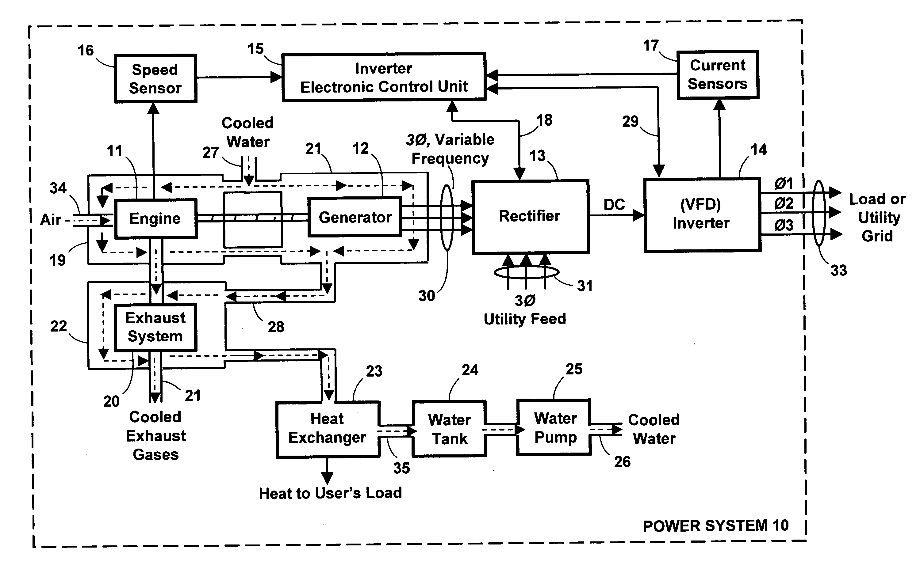
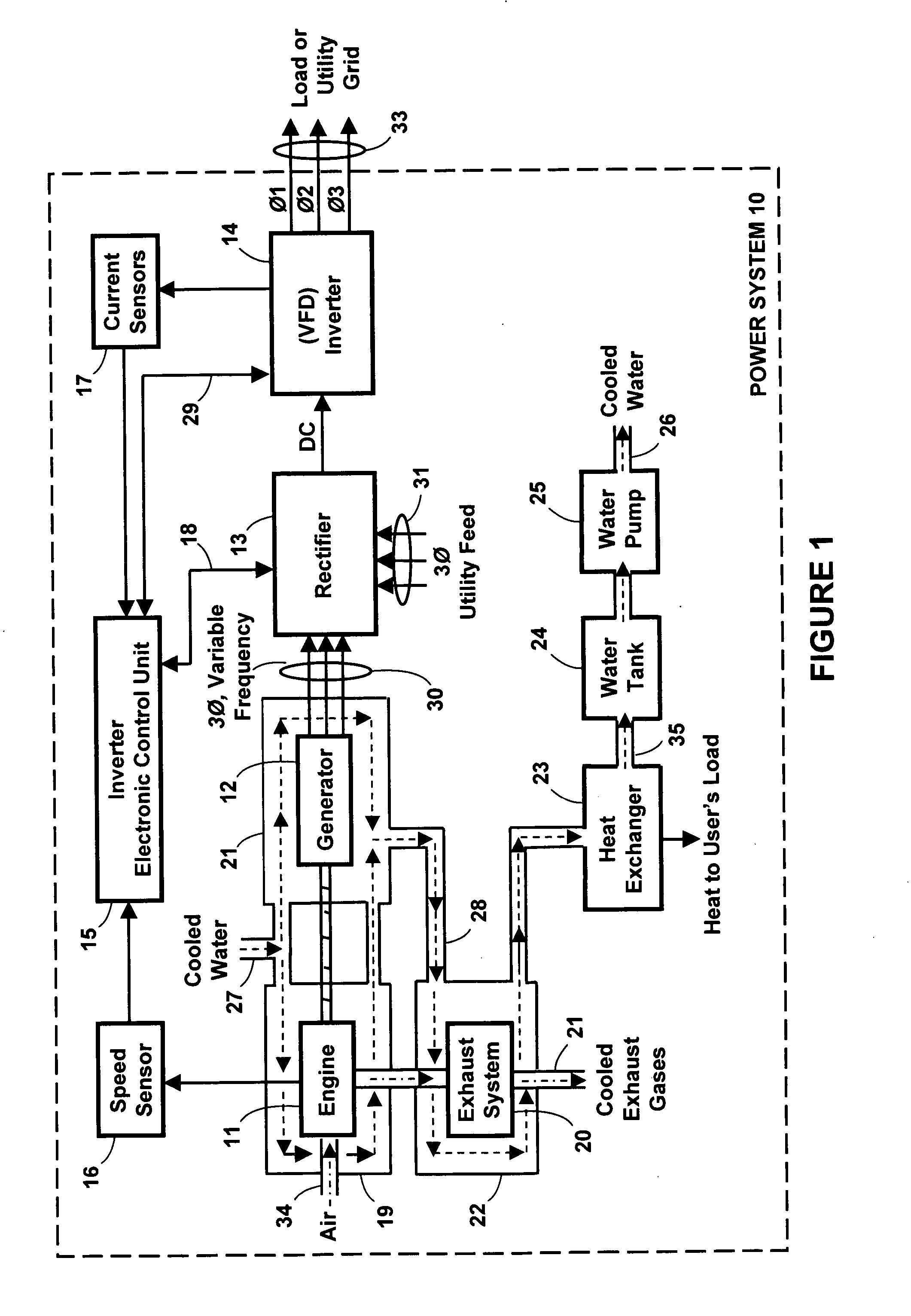
[0037] The invention comprises a novel Combined Heat and Power (“CHP”) electrical power generating system utilizing novel inverter control electronics for the simultaneous production of both electricity and heat. As described in the Summary of the Invention there are numerous advantages provided by the novel inverter control electronics as utilized with the novel engine driven CHP system. Generally those advantages are high reliability, high efficiency, compact size, and low cost. More specifically the above listed advantages are: (a) improved part-load efficiency, (b) the ability to operate the drive engine at lower speeds during reduced load periods, (c) the ability to operate at higher engine speeds for increased peak output, (d) simplified controls for paralleling multiple units, (e) reduced noise levels at part-load, (f) the ability to be coupled to higher non-linear loads and to start larger motors than a simple synchronous generator while running in standby, and (g) the abili...


PUM


Abstract

A combined heat and AC power generating system is disclosed having black start capability for the full time, simultaneous production of both electricity and heat. Heat generated within the system is captured and used for heating applications such as heating building air and tap water. The power generating system comprises an engine, generator, rectifier, variable frequency drive inverter, and inverter control electronics. The system provides improved efficiency and prolonged engine life by always operating the engine with its throttle fully open to obtain maximum efficiency and the engine is normally operated near its stall point. In this operating state the inverter control electronics adjust the power output from the inverter to control the speed of the engine. This is done by increasing the power output from the inverter when the power drawn by the load decreases. This causes the engine to operate closer to its stall point and it slows down. The power from the inverter is decreased when the power drawn by the load increases. This causes the engine to operate further from its stall point and it speeds up. The slight power changes to facilitate this operation will always be drawn from or distributed to the electric utility grid so there is no wasted power. The inverter control electronics are responsive to signals from loads such as refrigeration loads to cause the frequency of the inverter output to change to permit the refrigeration load to operate more efficiently.

Description

CROSS-REFERENCE TO RELATED APPLICATIONS [0001] This application claims the benefit of the following U.S. Provisional Patent Applications. [0002] Ser. No. 60 / 554,026, filed Mar. 16, 2004 in the name of Joseph B. Gehret. [0003] Ser. No. 60 / 554,031, filed Mar. 16, 2004 in the name of Joseph B. Gehret. [0004] Ser. No. 60 / 554,063, filed Mar. 16, 2004 in the name of Joseph B. Gehret. [0005] Ser. No. 60 / 553,737, filed Mar. 17, 2004 in the name of Joseph B. Gehret. [0006] Ser. No. 60 / 553,810, filed Mar. 17, 2004 in the name of Joseph B. Gehret.FIELD OF THE INVENTION [0007] This invention generally relates to the field of electric power generation, and more particularly to an engine driven generator and inverter apparatus for generating power in which the engine speed is controlled to accommodate different power loads drawn from the system and heat generated by the system is captured and used. BACKGROUND OF THE INVENTION [0008] In the prior art, electrical power generation systems comprising...

Claims


Application Information

Patent Timeline
IPC IPC(8): B60L1/02F02C6/00F02C6/18H02P3/00H02P5/00H02P9/04
CPCB60L3/003Y02T10/7088B60L2230/34B60L2240/36F02C6/18F02D29/06F02D41/0205F02D41/021F02D2250/24H02P9/04Y02E20/14Y02T10/7083Y02T90/12Y02T10/642B60L8/003B60L53/57Y02T10/64Y02T10/7072Y02T10/70
Inventor GEHRET, JOSEPH B. JR.
Owner TECOGEN
Why Eureka
Try Eureka