Enable pin using programmable hysteresis improvement

a technology of hysteresis improvement and pin enablement, applied in the field of dcdc converters, can solve problems such as the inability to use current sources

Inactive Publication Date: 2005-09-22
INTERSIL INC
View PDF6 Cites 15 Cited by
  • Summary
  • Abstract
  • Description
  • Claims
  • Application Information

AI Technical Summary

Benefits of technology

[0004] The present invention disclosed and claimed herein, in one aspect thereof, comprises an apparatus for providing programmable hysteresis control within a device. An enable pin of the device is configured to receive an input signal that enables or disables the associated device responsive to the input signal. A current source is

Problems solved by technology

However, in certain applications, a current source may not be used be

Method used


Image

  • Enable pin using programmable hysteresis improvement
  • Enable pin using programmable hysteresis improvement
  • Enable pin using programmable hysteresis improvement

Examples


Embodiment Construction

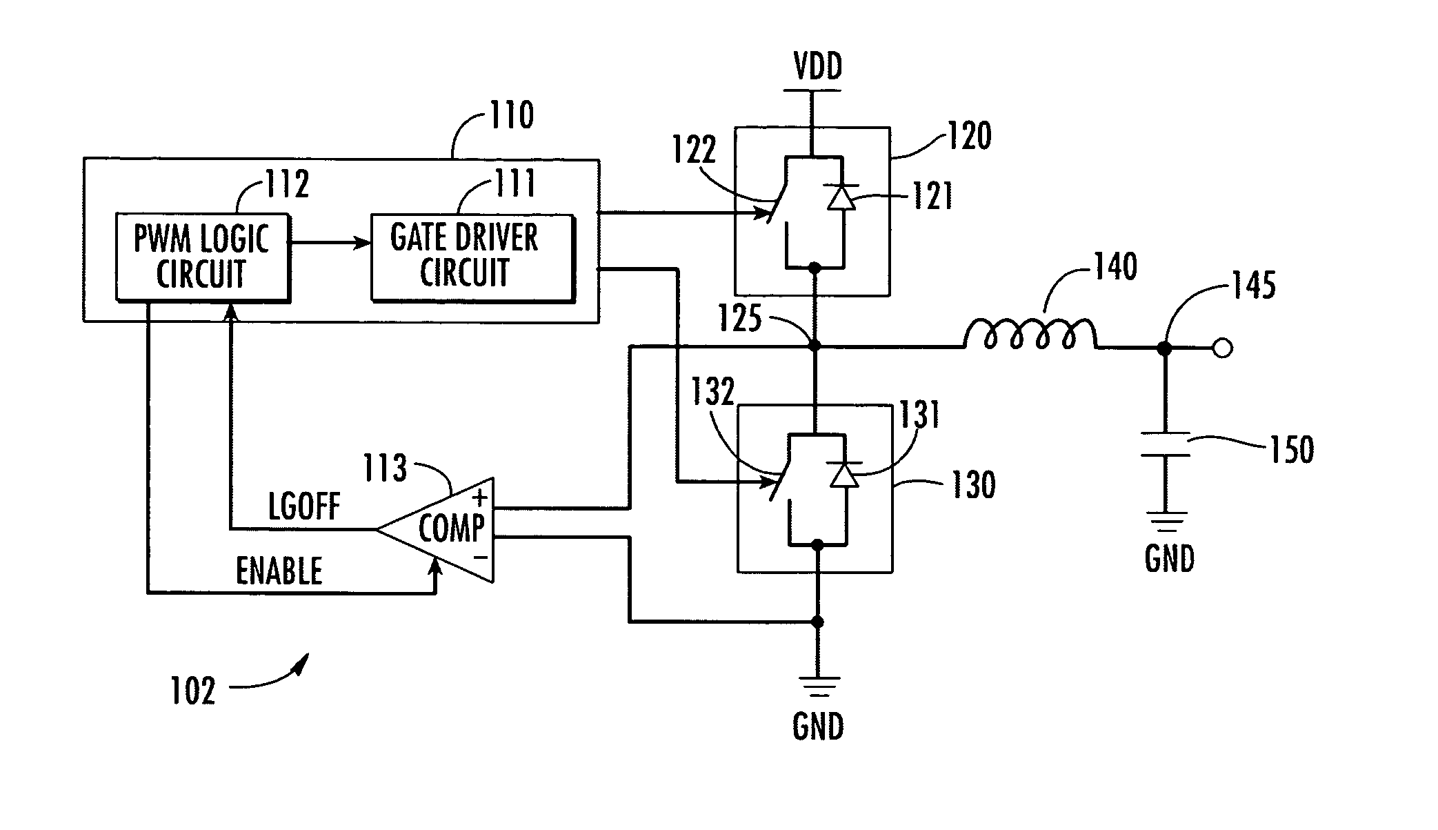
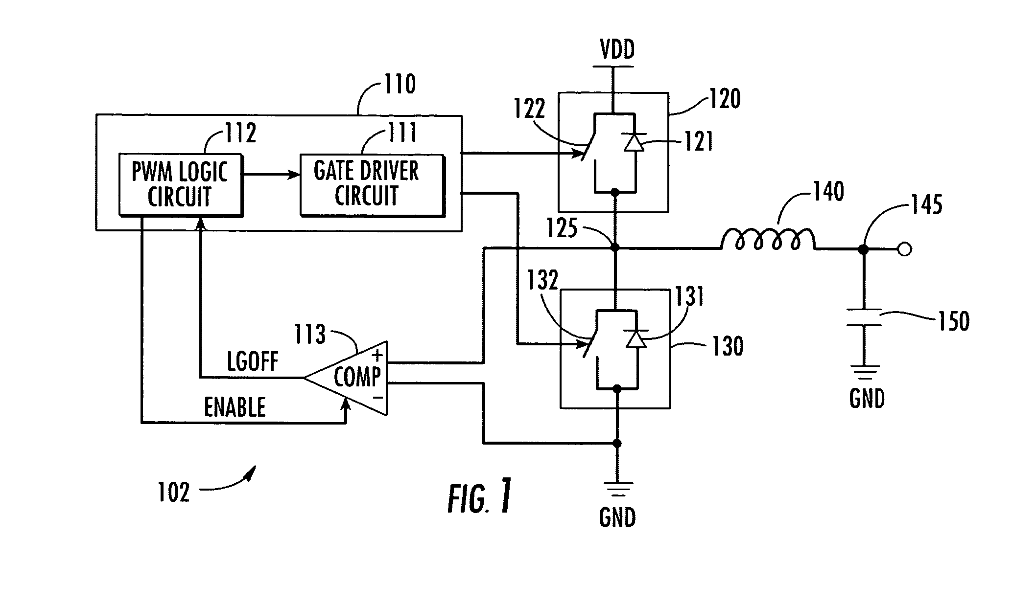
[0009] Referring now to the drawings, and more particularly to FIG. 1, wherein there is illustrated the general circuit configuration of a conventional DC-DC voltage converter as comprising a DC-DC controller, which fully controls the turn on and turn off of a pair of electronic switching devices, respectively, shown as an upper FET pass element 120 and a lower FET pass element 130. These FET switching devices have their drain / source paths coupled in between first and second reference voltages VDD and ground (GND). Each pass element contains a controllable switch shown as an upper switch 122 and a lower switch 132. The upper pass element contains a body diode 121 in parallel with the drain / source path such that the reverse current flows through the diode body toward VDD. A lower pass element 130 contains a body diode 131 in parallel with the drain / source path such that the reverse current flows through the body diode from ground. A common or phase voltage 125 between the two power F...


PUM


Abstract

An apparatus for providing programmable hysteresis control using an enable pin of a device is disclosed. An enable pin is configured to receive an input signal to enable and disable an associated device responsive to the input signal. A current sink is attached to the enable pin and is responsive to circuitry that disables the current sink responsive to application of the input signal at a first voltage level and enables the current sink responsive to application of the input signal at a second voltage level.

Description

CROSS-REFERENCE TO RELATED APPLICATIONS [0001] This application claims priority from pending U.S. Provisional Patent Application Serial No. 923 (Atty. Dkt. No. INTS-26,694) entitled “PROGRAMMABLE HYSTERESIS VEMENT” filed on Mar. 17, 2004.TECHNICAL FIELD OF THE INVENTION [0002] The present invention relates to DC-DC converters, and more particularly, to an enable pin of a DC-DC converter or similar device. BACKGROUND OF THE INVENTION [0003] The enable pin of a DC-DC converter or other type of device may be used for voltage monitoring in some applications. Existing designs establish a precision threshold with which to enable a DC-DC converter or similar device given a particular application requirement. Prior art designs use a current source that sources current into the enable pin after logical assertion of the enable signal to the enable pin to provide hysteresis control. However, in certain applications, a current source may not be used because the enable pin is being multiplexed t...

Claims


Application Information

Patent Timeline
IPC IPC(8): H02M3/158H03K5/153H03K5/22
CPCH02M3/1588H02M1/0012H02M1/0038Y02B70/10
Inventor MEHAS, GUSTAVOCHEUNG, CHUNDAY, BRANDON
Owner INTERSIL INC
Why Eureka
Try Eureka