Reference voltage generation circuit, data driver, display device, and electronic instrument

a reference voltage generation and data driver technology, applied in the direction of instruments, static indicating devices, code conversion, etc., can solve the problems of limited output pitch of the data line driver circuit which drives the data line, and power consumption cannot be reduced

Inactive Publication Date: 2005-09-22
SEIKO EPSON CORP
View PDF6 Cites 38 Cited by
  • Summary
  • Abstract
  • Description
  • Claims
  • Application Information

AI Technical Summary

Benefits of technology

[0011] wherein the first and second voltage supply circuits supply at least one of the high-potential-side voltage and the low-potential-side voltage to the two opposite ends of the resistor circuit, respectively, by switching the high-potential-side voltage and the low-potential-side voltage for each of color components which form one pixel, the high-potential-side voltage and the low-potential-side voltage being provided for each of the color components, and
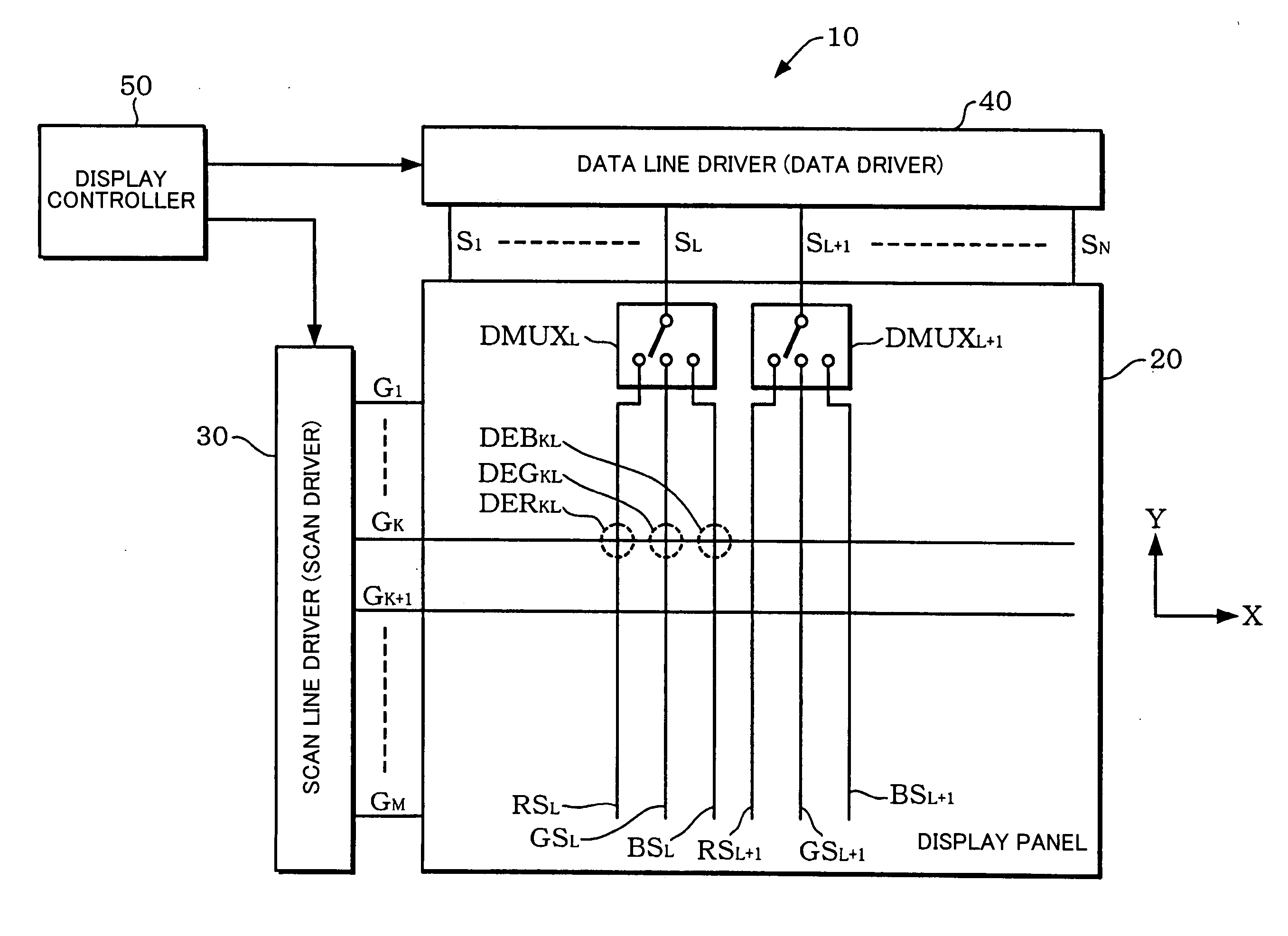
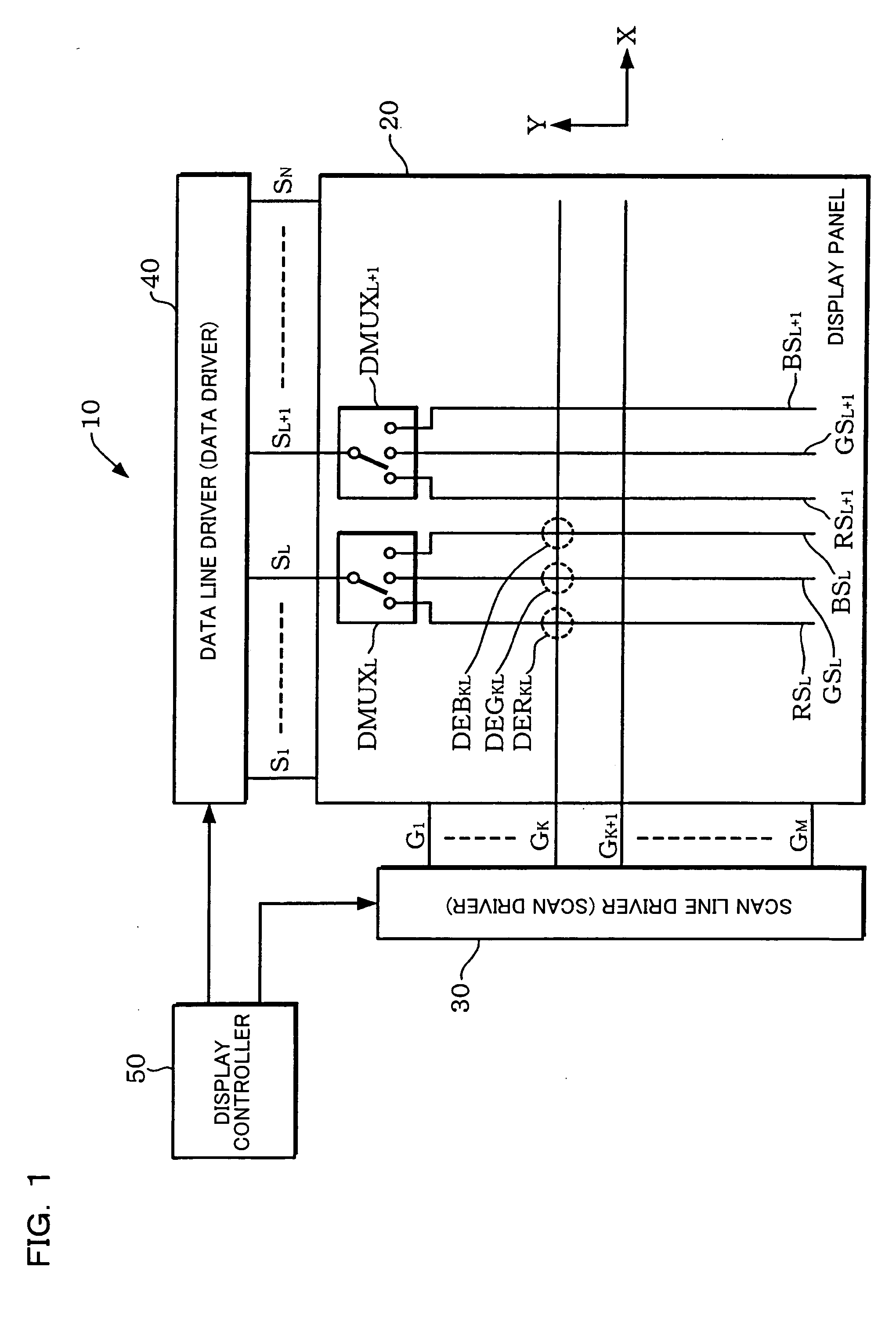
[0069] In this embodiment, since the gamma correction resistor circuit supplies the reference voltages to the reference voltage signal lines used in common for the first and second driver sections which respectively drive the first and second data lines of the electro-optical device, it is unnecessary to provide the reference voltage generation circuits in data line units, whereby the data line output pitch of a data driver including the reference voltage generation circuit is prevented from being limited. This makes it possible to contribute to providing a data driver which deals with an increase in definition.
[0020] a multiplexer circuit which multiplexes the grayscale data for each of the color components of one pixel by time division;
[0062] An embodiment of the present invention has been achieved in view of the above-described technical problem, and may provide a reference voltage generation circuit, a data driver, a display device, and an electronic instrument for performing gamma correction while reducing power consumption without limiting the output pitch to data lines of a display panel.
[0002] The present invention relates to a reference voltage generation circuit, a data driver, a display device, and an electronic instrument.
[0004] In recent years, an electroluminescent (hereinafter abbreviated as “EL”) device using an EL element has attracted attention. In particular, since an organic EL device including an EL element formed by using a thin film of an organic material is a self-emission type, a backlight becomes unnecessary, whereby a wide viewing angle is realized. Moreover, since the organic EL device has a high response speed in comparison with a liquid crystal panel, a color video display can be easily realized using a simple configuration. In the case where such a display device is provided as a display section of a portable telephone, an image display rich in color tone due to an increase in the number of grayscales is required.

Problems solved by technology

In particular, since an organic EL device including an EL element formed by using a thin film of an organic material is a self-emission type, a backlight becomes unnecessary, whereby a wide viewing angle is realized.
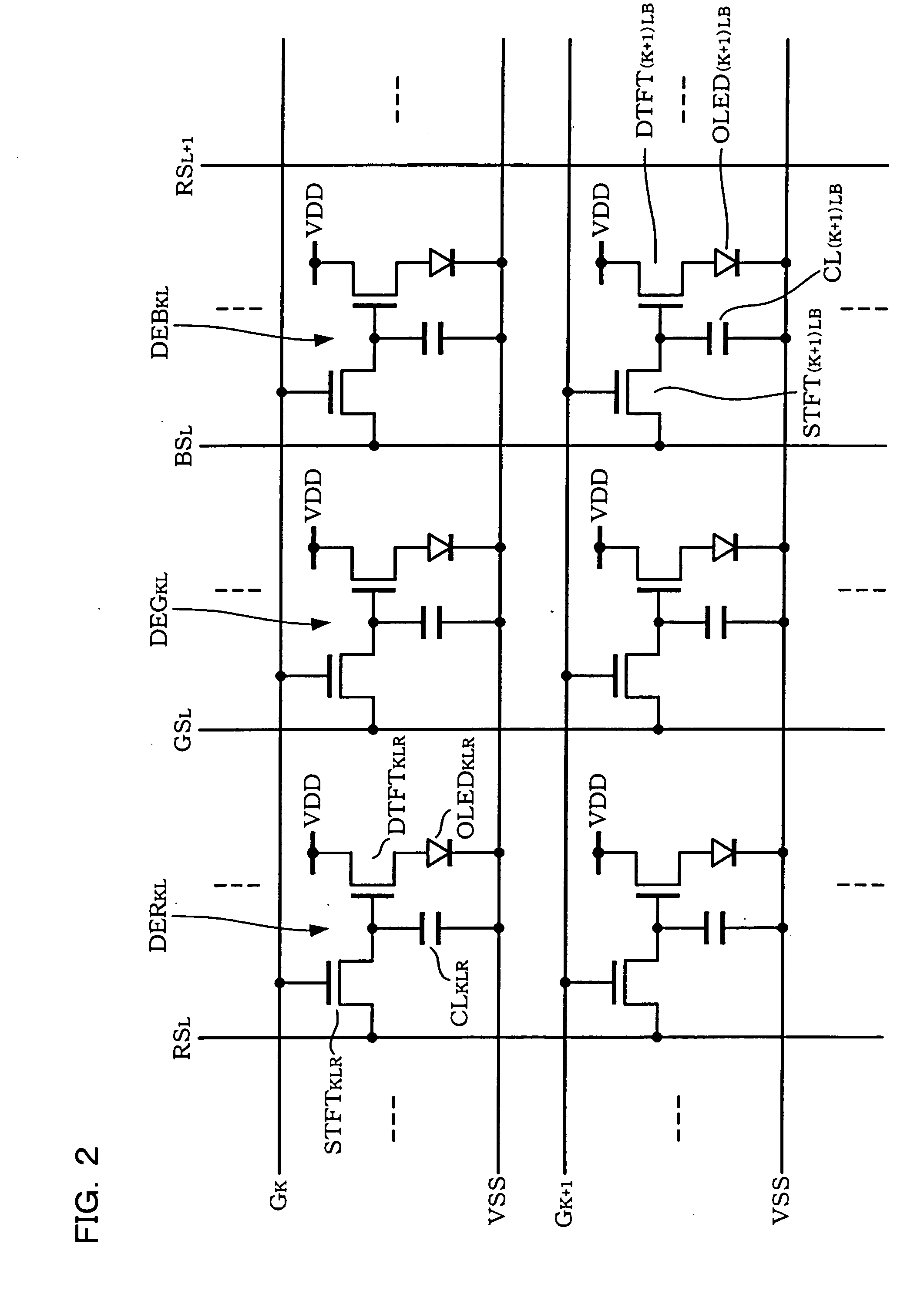
However, in the case where gamma correction circuits which realize such a gamma correction are provided in units of data lines of a panel including organic EL elements arranged in the shape of a matrix, the output pitch of a data line driver circuit which drives the data lines is limited.
Moreover, since current flows through the resistor element of each gamma correction circuit, power consumption cannot be reduced (see FIGS. 1 and 6 of Japanese Patent Application Laid-open No. 2001-290457, for example).

Method used


Image

  • Reference voltage generation circuit, data driver, display device, and electronic instrument
  • Reference voltage generation circuit, data driver, display device, and electronic instrument
  • Reference voltage generation circuit, data driver, display device, and electronic instrument

Examples


Embodiment Construction

[0062] An embodiment of the present invention has been achieved in view of the above-described technical problem, and may provide a reference voltage generation circuit, a data driver, a display device, and an electronic instrument for performing gamma correction while reducing power consumption without limiting the output pitch to data lines of a display panel.

[0063] An embodiment of the present invention provides a reference voltage generation circuit for generating a plurality of reference voltages including a reference voltage selected corresponding to grayscale data, the reference voltage generation circuit including: [0064] a gamma correction resistor circuit which includes a resistor circuit and outputs the reference voltages generated by resistively dividing voltages of two opposite ends of the resistor circuit to a plurality of resistive division nodes; and [0065] first and second voltage supply circuits which supply a high-potential-side voltage and a low-potential-side v...


PUM


Abstract

A reference voltage generation circuit includes a gamma correction resistor circuit which outputs reference voltages generated by resistively dividing voltages of two opposite ends of a resistor circuit to resistive division nodes, and high-potential-side-voltage and low-potential side-voltage supply circuits which supply a high-potential-side voltage and a low-potential-side voltage to the two opposite ends, respectively. The high-potential-side-voltage and low-potential side-voltage supply circuits supply the high-potential-side voltage and the low-potential-side voltage to the two opposite ends, respectively, by switching the high-potential-side voltage and the low-potential-side voltage for each of color components which form one pixel, the high-potential-side voltage and the low-potential-side voltage being provided for each of the color components. The gamma correction resistor circuit supplies the reference voltages switched for each of the color components to reference voltage signal lines to be selected as inputs of driver sections which drive data lines of an electro-optical device.

Description

[0001] Japanese Patent Application No. 2004-79051, filed on Mar. 18, 2004 is hereby incorporated by reference in its entirety. BACKGROUND OF THE INVENTION [0002] The present invention relates to a reference voltage generation circuit, a data driver, a display device, and an electronic instrument. [0003] A reduction in size and an increase in definition have been demanded for a display device represented by an electro-optical device such as a liquid crystal device. A liquid crystal device realizes a reduction in power consumption and is generally provided in a portable electronic instrument. [0004] In recent years, an electroluminescent (hereinafter abbreviated as “EL”) device using an EL element has attracted attention. In particular, since an organic EL device including an EL element formed by using a thin film of an organic material is a self-emission type, a backlight becomes unnecessary, whereby a wide viewing angle is realized. Moreover, since the organic EL device has a high r...

Claims


Application Information

Patent Timeline
Patent Type & Authority Applications(United States)
IPC IPC(8): G09G3/20G09G3/36G09G3/30G09G3/32G11C7/00G11C7/10H03M1/76H05B44/00
CPCG09G3/3233G09G3/3291G09G2300/0842G09G2310/027G09G2310/0297G11C7/106G09G2330/021G09G2330/028G11C7/1051G11C7/1057G09G2320/0276
Inventor MORITA, AKIRA
Owner SEIKO EPSON CORP
Why Eureka
Try Eureka