Method of producing self-aligned mask in conjuction with blocking mask, articles produced by same and composition for same

US20050208430A1Inactive Publication Date: 2005-09-22IBM CORP

Image

  • Method of producing self-aligned mask in conjuction with blocking mask, articles produced by same and composition for same
  • Method of producing self-aligned mask in conjuction with blocking mask, articles produced by same and composition for same
  • Method of producing self-aligned mask in conjuction with blocking mask, articles produced by same and composition for same

Examples


Embodiment Construction

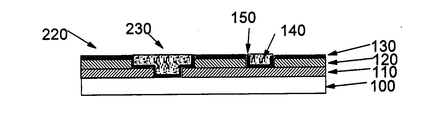
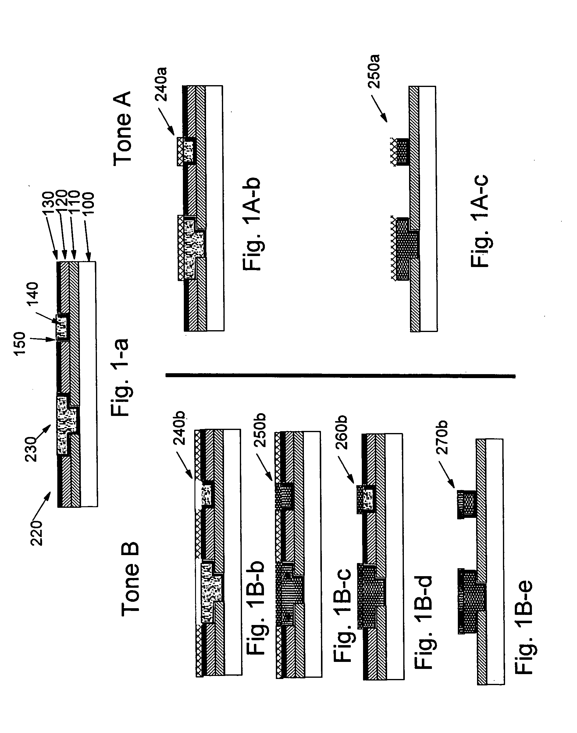
[0042] The present invention provides a method of forming a patterned layer on a substrate having thereon a pre-patterned film. The method includes the steps of: applying onto the substrate having thereon a pre-patterned film a solution of a masking material in a carrier; removing at least a portion of the carrier to form a coating; patternwise exposing the coating to radiation in conjunction with a blocking mask pattern so that the radiation that is passed through the blocking mask is transmitted through the coating and is reflected back to the coating to produce a latent image in the layer having exposed and unexposed regions with a given spatial intensity distribution commensurate with the convolution of the block mask pattern and the spatial reflectivity map of the substrate having thereon a pre-patterned film; and developing the exposed coating to reveal a mask pattern in the coating commensurate with the spatial intensity distribution generated during exposure to radiation; an...


PUM


Abstract

A method of forming a self aligned pattern on an existing pattern on a substrate including applying a coating of a solution containing a masking material in a carrier, the masking material being either photo or thermally sensitive; performing a blanket exposure of the substrate; and allowing at least a portion of the masking material to preferentially develop in a fashion that replicates the existing pattern of the substrate. The existing pattern includes a first set of regions of the substrate having a first reflectivity and a second set of regions of the substrate having a second reflectivity different from the first composition. The first set of regions can include one or more metal elements and the second set of regions can include one or more dielectrics. Structures made in accordance with the method. A low resolution mask is used to block out regions over the substrate. Additionally, the resist can be applied over another masking layer that contains a separate pattern.

Description

BACKGROUND OF THE INVENTION [0001] 1. Field of the Invention [0002] This invention relates to the production of patterns on a substrate having regions with different chemical identities. More particularly, it relates to a method of producing fine patterns on substrates used in, for example, the microelectronics industry on which electronic devices are fabricated. The present invention also relates to devices fabricated in accordance with these methods. [0003] 2. Description of the Related Art [0004] A number of applications and technologies involve structures having a well-defined arrangement of distinct regions. Normally, these structures are defined by patterning processes such as lithography, embossing, and stamping, and have length scales ranging from nanometers to several microns to even millimeters. In many of these systems it may be necessary or beneficial to apply an additional component or treatment to or above only a subset of the chemically district regions. One commonly ...

Claims


Application Information

Patent Timeline
22 Sep 2005
Publication
US20050208430A1
IPC
G03F7/00; G03F7/20
CPC
G03F7/2022
Inventors
COLBURN, MATTHEW E.; NITTA, SATYANARAYANA V.