Method of apparatus for collecting micromaterial

a micromaterial and apparatus technology, applied in the field of micromaterial collection apparatus, can solve the problems of difficult application to microorganisms several micrometers in size, large time and expense, and difficult to achieve the effect of high-speed recovery and accelerating separation speed

Inactive Publication Date: 2005-09-22
JAPAN SCI & TECH CORP
View PDF11 Cites 20 Cited by
  • Summary
  • Abstract
  • Description
  • Claims
  • Application Information

AI Technical Summary

Benefits of technology

[0046] Conventional cell sorters separate cells by inducing serial flows, but the present invention can select randomly dispersed target materials by two dimensionally spreading a sample and comparing the properties. By expanding the observation zone, 10,000 to 40,000 micromaterials can be compared and sorted in a single pass using this method, accelerating the separation speed. In addition, a selected target material can be attached to the interior of a microchip or a micromanipulator or retained inside a suctioned pipette chip making high speed recovery simple to execute when necessary.
[0047] The present invention is illustrated using the examples shown below, but the examples are not intended to limit the present invention.

Problems solved by technology

However, the method using micropipettes requires skilled techniques select, sort and recover high purity micro samples microscopically, and also requires enormous time and expense to implement the practice.
While the method using cell sorters proved to be effective on target materials that are several tens of microns in size but were difficult to apply to microorganisms several micrometers in size.
Cell sorters also involved sequential separation work on samples lined up in a row and could not be used to quickly remove optionally selected targets from randomly dispersed samples.
However, microorganisms were transported using a direct laser trap, and the procedure was accompanied by the risk of microbial damage.
However, complicated operations presented problems in actual applications.

Method used


Image

  • Method of apparatus for collecting micromaterial
  • Method of apparatus for collecting micromaterial
  • Method of apparatus for collecting micromaterial

Examples


example 2

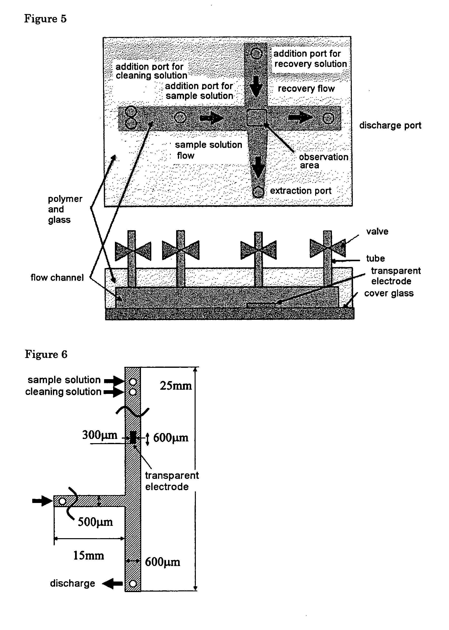
[0052] Schematic diagrams of the microchips used in the present examples are shown in FIGS. 5 and 6.

[0053] These microchips are equipped with two intersecting flow channels. The form for these two flow channels were created using microtooling, and the microfluid chips were shaped from PDMS (polydimethylsiloxane). The two flow channels intersected forming a cross in the microchip shown in FIG. 5, and the two flow channels intersected forming a T in the microchip shown in FIG. 6. A single discharge port functioned to discharge both a sample and a cleaning solution.

[0054] One flow channel was used to add a sol / gel phase transition substance containing a target material and to move water used to clean unnecessary materials other than subsequently fixed target materials. The other flow channel was used to recover the fixed target material.

[0055] The intersection of the two flow channels (an observation zone) was observed using an inverted optical microscope (Olympus Co., IX70), and th...

example 3

[0061] A microchip similar to the one described in Example 1 with the exception of having transparent electrodes (ITO) located in top and lower sections of an observation zone was used.

[0062] A mixture of a sample and methylcellulose similar to the one described in Example 1 was added to this microchip.

[0063] Both transparent electrodes were warmed by passing electrical current, and the sample and impurities were entirely immobilized once. The target material vicinity was subsequently irradiated using a laser in the same manner as described in Example 1. The design is shown in FIG. 8. The power to the transparent electrodes was subsequently terminated, and water was added from a cleaning water addition port to remove unnecessary materials. The target material remaining was subsequently recovered.

[0064] One merit of the current method is that a sample not near the bottom surface can be immobilized in the environment since the immobilization occurs through localized heating using b...

example 4

[0065] In the present example, a target material was immobilized by heating that combined electrical overheating of an electrode with localized heating using laser irradiation. A schematic diagram of this microchip is shown in FIG. 9.

[0066] This microchip was positioned on a microscope stage. The observation zone could be changed according to the observation magnification of the microscope, and a broad area could be observed by moving the stage. A large amount of sample can be treated by preparing multiple numbers of electrodes, and the work efficiency can be improved. In order to realize immobilization through electrical overheating of an electrode, only one target material of about several microns can be immobilized and, therefore, the number of electrodes needed to be increased. Many electrodes are needed to remove only one target material from several thousands to several tens of thousands of micromaterial samples, and the system could become complex. Therefore, multiple number...


PUM

PropertyMeasurementUnit
temperatureaaaaaaaaaa

Abstract

A substance (for example, methylcellulose) that undergoes a reversible gel to sol phase transition is utilized in a recovery method for specific micromaterials such as DNA molecules, cells, microorganisms and the like, approximately several μm in size, from a mixture containing other micromaterials, and a micromaterial is accurately and conveniently recovered. The present invention is a method of recovering a desired micromaterial in a system comprising a medium that undergoes a reversible phase transition between a sol and a gel, a support material and micromaterials, comprising the steps of converting the medium surrounding the micromaterial to be recovered into a gel locally to immobilize said micromaterial on said support along with the gelled medium, removing the medium and micromaterials not immobilized on said support material and converting the gelled medium to a sol to recover the micromaterial.

Description

TECHNICAL FIELD [0001] The present invention relates to a method to recover a specific micromaterial from among numerous micromaterials and a device thereof, more specifically, to a method to recover specific micromaterials such as DNA molecules, cells, microorganisms and the like from among other micromaterials present. PRIOR ART [0002] The conventional methods to recover specific micromaterials such as DNA molecules, cells, microorganisms and the like from other micromaterials present includes the removal of a target material from Petri dishes using micropipettes while observing the material under an optical microscope and the use of cell sorters [Nihon Kikai Gakkai Ronbunshu, Vol 67, Edition c, pp. 146-153 (January 2001), Electrophoresis 2001, 22, 283-288]. However, the method using micropipettes requires skilled techniques select, sort and recover high purity micro samples microscopically, and also requires enormous time and expense to implement the practice. While the method us...

Claims


Application Information

Patent Timeline
Patent Type & Authority Applications(United States)
IPC IPC(8): B01L3/00C12M1/34C40B60/14G01N1/28G01N15/14
CPCB01J2219/00495G01N2015/1497B01J2219/00644B01L3/502753B01L3/502761B01L2200/0668B01L2300/0816B01L2300/1827B01L2300/1861B01L2300/1872B01L2400/0677C40B60/14G01N15/1463G01N2001/282G01N2001/284G01N2001/2886B01J2219/00527
Inventor ARAI, FUMIHITOFUKUDA, TOSHIOICHIKAWA, AKIHIKOKATSURAGI, TOHORU
Owner JAPAN SCI & TECH CORP
Why Eureka
Try Eureka