Generally speaking, the magnitude or power of a
radio signal weakens as it travels from its source.
However, the multipath phenomenon encountered in indoor RF environments does present certain difficulties in locating wireless nodes, since reflection and absorption of RF signals affects the correlation between signal strength and proximity.
While the
RADAR system works for its intended objective, even in this
system, location accuracy decreases with the error in detecting the strength of RF signals.
As discussed below, however, the error injected by errors in signal strength detection can inject large amounts of error in computing the location of a wireless node, especially where the detected signal, at the
radio receiver, is weak.
Still further, while the
RADAR system allows a
mobile station to track its own location, it does not disclose a system that allows the WLAN infrastructure to track the location of wireless nodes, such as rogue access points.
Moreover, individual differences as to how two different wireless nodes detect and report signal strength can cause errors in location, since the Radio Maps assume no error in such measurements.
Still further, while the
RADAR system allows a
mobile station to track its own location, it does not disclose a system that allows the WLAN infrastructure to track the location of wireless nodes, such as rogue access points.
This paradigm shift, however, presents certain problems.
Estimating location based on signals transmitted by a wireless node, however, can be problematic, since transmit power can vary among wireless device manufacturers, and / or may be individually configured by the mobile user.
Furthermore, these approaches also assume a uniform transmit power for the wireless nodes in light of the fact that legal regulations, as well as current
chip set technology, generally places an upper limit on transmit power.
These two assumptions, however, can significantly
impact the accuracy of locating a wireless node.
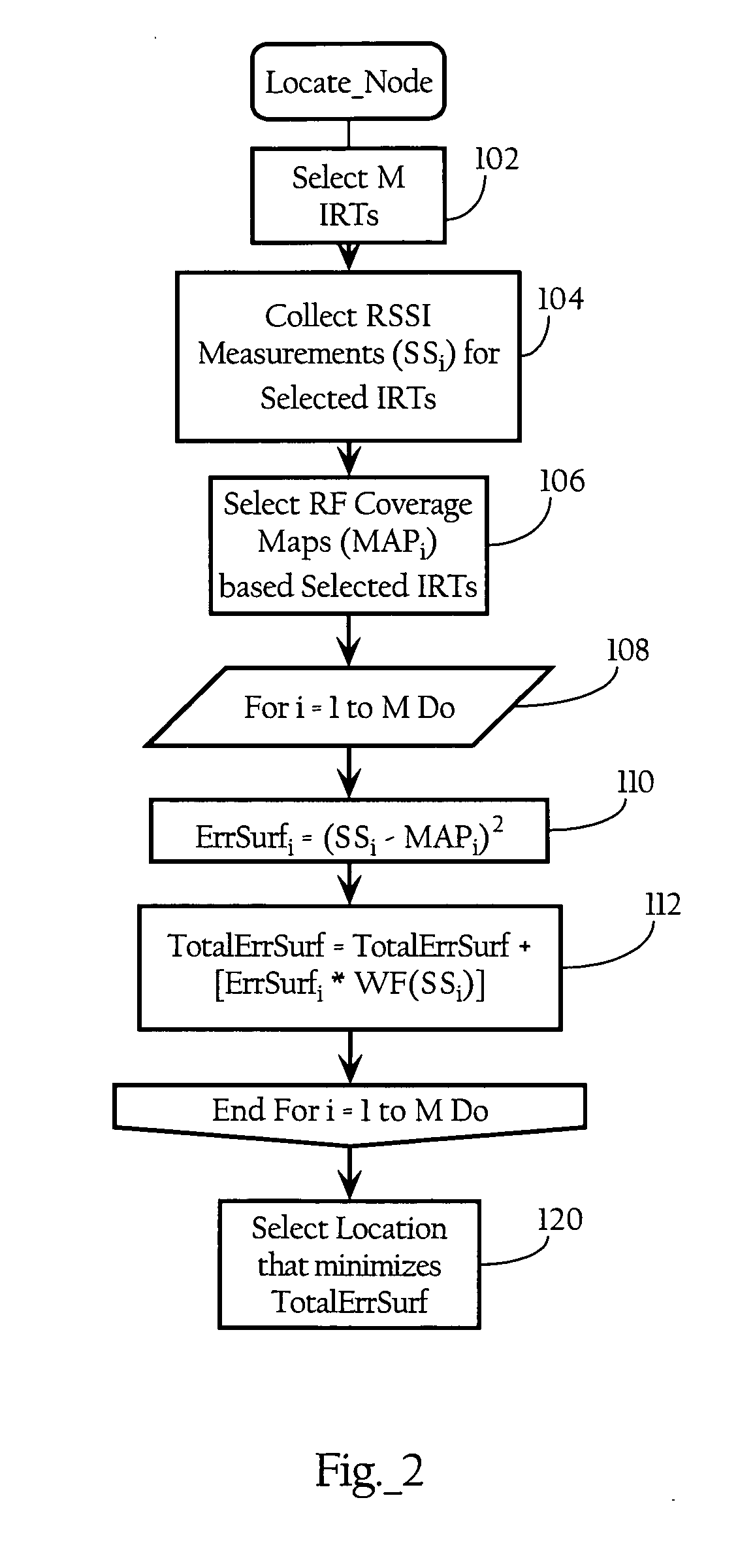
In many situations, however, the measured signal strengths, RSSIap1 RSSIap2, and RSSIap3, do not match the signal strengths recorded in the coverage maps MAPap1, MAPap2, MAPap3 at any one location.
However, a change in the wireless node's transmit power (or, in the RADAR system, inaccuracies in detecting signal strength by the wireless nodes) will adversely affect the accuracy of this metric.
It also creates unpredictable error with changes in transmit power.
Similar problems will occur for a fixed error in the “link or
path loss symmetry” where the
path loss from access point to wireless node differs from the path loss from wireless node to access point by some fixed amount due to propagation characteristics, vantage point, and the like.
In addition, sources of RF interference typically have unknown transmit powers, and may only partially overlap the
frequency band in which wireless nodes operate.

