
Inspection method and system and production method of mounted substrate

Inactive Publication Date: 2005-09-22
ORMON CORP
View PDF6 Cites 16 Cited by
  • Summary
  • Abstract
  • Description
  • Claims
  • Application Information

AI Technical Summary

Benefits of technology

[0013] By this method of inspection, each inspection apparatus on a downstream side can make use of the inspection data obtained on the actual target substrate being inspected by an inspection apparatus on the upstream side. Thus, a judgment can be made according to the specification of the actual target substrate and the data obtained by measurements can be utilized more effectively.
[0031] According to this invention, inspections can be carried out more reliably because each time a substrate being produced is inspected during its production processes, an image of the same substrate or data produced in an earlier executed production step are used.

Problems solved by technology

In reality, however, there are small fluctuations in the positions of lands due to displacements of resist material in the production step of printed circuit boards, and the position and the size of a land are not always exactly the same as described as the design data.
On the other hand, the density of components mounted on each substrates is increasing and, as components are made smaller, the lands on the substrates, too, tend to become smaller.
Thus, if the solder is printed away from its intended land position even by a small distance, there is the danger of making it very difficult to mount and solder a component properly.
If standard reference values for evaluating an inspection area are set on the basis of the substrate design data, it may be not possible to detect the displacement of a printed position of a solder piece.
In the case of a substrate after the solder printing step, for example, although the solder is printed at a standard position according to the substrate design data, there is a possibility of displacement greater than an allowable limit between the land and the solder if the land is displaced from its standard position according to the substrate design data.

Method used


Image

  • Inspection method and system and production method of mounted substrate
  • Inspection method and system and production method of mounted substrate
  • Inspection method and system and production method of mounted substrate

Examples


Embodiment Construction

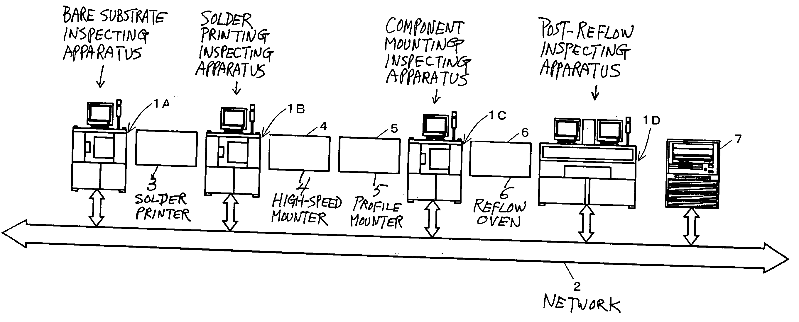
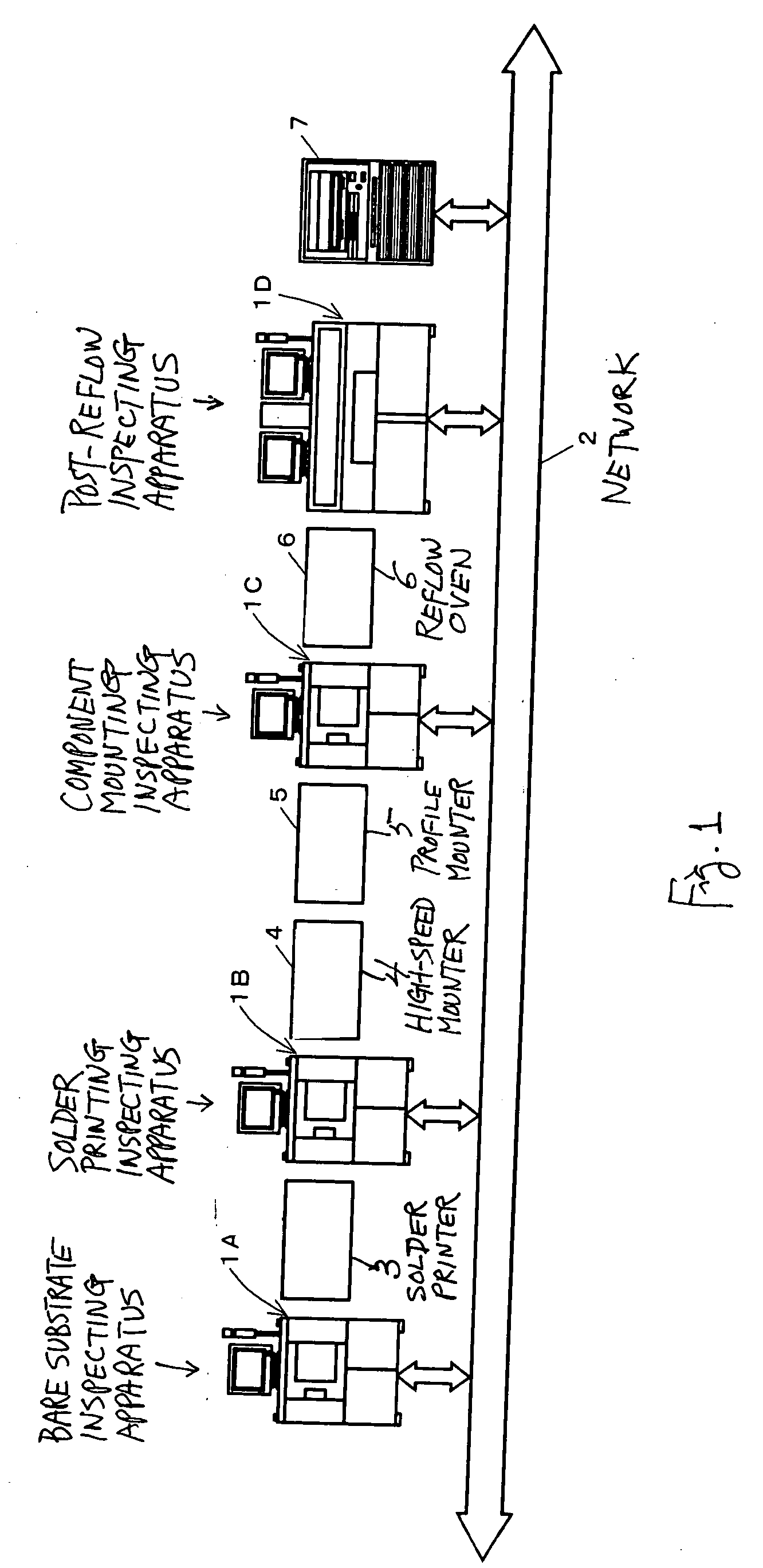
[0045]FIG. 1 shows a production line for substrates to which the present invention is applied, including production apparatus such as a solder printer 3, a high-speed mounter 4, a profile mounter 5 and a reflow oven 6, a plurality of inspection apparatus 1 and a data processor 7. The inspection apparatus 1 are set at four different positions, one (indicated by symbol 1A) on the upstream side of the solder printer 3, another (indicated by symbol 1B) between the solder printer 3 and the high-speed mounter 4, a third (indicated by symbol 1C) between the profile mounter 5 and the reflow oven 6, and a fourth (indicated by symbol 1D) on the downstream side of the reflow oven 6.

[0046] The data processor 7 is a computer having a hard disk with a large capacity and may have a terminal device (not shown) such as a personal computer connected to it. Each of the inspection apparatus and the data processor 7 are set such that they can communicate among themselves through a network line 2 such a...


PUM


Abstract

Substrates with components mounted thereon are produced by a plurality of sequentially performed production steps. Inspection apparatus are provided, each associated with different one of these production steps including the last step. These inspection apparatus communicate among themselves and each use an image of a target substrate to be inspected taken after or data obtained in an earlier executed production step.

Description

[0001] Priority is claimed on Japanese Patent Applications P2004-056757 filed Mar. 1, 2004 and P2005-040703 filed Feb. 17, 2005. BACKGROUND OF THE INVENTION [0002] This invention relates to a method and a system of inspection in the production of substrates each having components mounted thereonto. The production process includes a plurality of steps but an inspection is carried out at the end of the last of the production steps or in a plurality of steps including the last production step by an image processing process. The invention also relates to a production method of such mounted substrates by carrying out such inspection processes. [0003] Examples of common production step for mounted substrates include the solder printing step for printing cream solder on a printed circuit board, the component mounting step for mounting components at positions where cream solder has been applied and the soldering step for heating the substrate after the component mounting step has been carri...

Claims


Application Information

Patent Timeline
IPC IPC(8): G01B11/00G01N21/956H05K3/34H05K13/00H05K13/08
CPCH05K13/08H05K13/0817H05K13/083
Inventor ISHIBA, MASATOKURIYAMA, JUNMURAKAMI, KIYOSHIYOTSUYA, TERUHISA
Owner ORMON CORP
Features
  • Generate Ideas
  • Intellectual Property
  • Life Sciences
  • Materials
  • Tech Scout
  • Unparalleled Data Quality
  • Higher Quality Content
  • 60% Fewer Hallucinations
Learn More