Digital system clock control

a digital system and clock control technology, applied in the field of digital systems, can solve the problems of only wasting power, consuming more power, and consuming more power

Inactive Publication Date: 2005-09-22
NOKIA CORP
View PDF17 Cites 11 Cited by
  • Summary
  • Abstract
  • Description
  • Claims
  • Application Information

AI Technical Summary

Benefits of technology

[0014] The arrangement of the invention provides significant advantages especially in mobile devices. One advantage is that significant power savings can be achieved by the proposed arrangement, because the processor block does not need to wake up every time a functional block wakes up. The arrangement enables longer operation times of battery operated devices, such as longer standby time especially when the Bluetooth block is enabled, longer usage time, for example, for a calendar, short message service (SMS) and note editing, and such low activity use case. Another advantage is that the arrangement is relatively easy and cheap to implement and maintain on account of minor investments in devices and technical simplicity of the implementation.

Problems solved by technology

The blocks usually consume a significant amount of power whenever the block is active.
However, there is a problem in current digital architectures of mobile devices, for example, that the system typically comprises only one system oscillator, whose enabling can typically only be carried out by a specialized processor block, such as a cellular processor block, which is arranged to send a system clock request to a block controlling the system oscillator, such as a power management unit.
The more functional blocks the system comprises and the more often the functional blocks need to wake up, the more often the processor block has to wake up and the more power is consumed.
In most cases the Bluetooth block does not even have any data to send to the processor block, and therefore, the wake-up of the processor block can be considered as a redundant operation and thus, power is only wasted, which shortens the battery life of the mobile device.

Method used


Image

  • Digital system clock control
  • Digital system clock control
  • Digital system clock control

Examples


Embodiment Construction

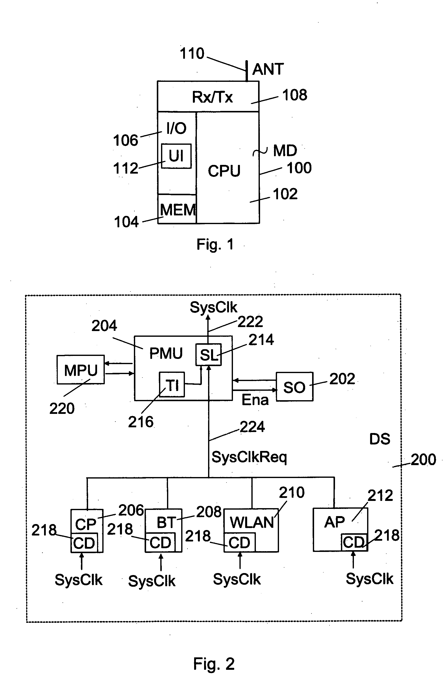
[0019]FIG. 1 describes some basic features of a mobile device MD (100), such as a mobile phone, a laptop or a PDA device (Personal Digital Assistant device) in which the invention can be applied. Here the mobile device MD generally refers to a wireless terminal capable of processing data in digital form. The mobile device MD comprises a central processing unit CPU (102) comprising one or more processors, a memory MEM (104), an input / output system I / O (106) and a receiver-transmitter Rx / Tx (108), which is arranged to receive and transmit data according to various data transfer protocols via an antenna ANT (110). The requested data needed is stored in the memory MEM, which typically comprises read memory, such as ROM (Read Only Memory) for storing applications used for controlling the central processor unit CPU and other data to be stored, and write memory, such as RAM (Random Access Memory) and / or FLASH memory for processing temporary data. The mobile device MD communicates outwards,...


PUM


Abstract

A digital system, a method implemented by the system and a mobile device, in which the system can be applied, the system including a system oscillator for providing a system main clock signal, a control block for controlling at least the power management of the digital system and one or more functional blocks, whereof at least one is arranged to detect a need for a system clock. At least one functional block is arranged to send at least one system clock request signal to the control block, which in turn is arranged to enable the system oscillator to provide the system clock signal in response to receiving the system clock request signal. When the system clock signal appears, the at least one functional block is arranged to detect the system clock signal.

Description

FIELD OF THE INVENTION [0001] The invention relates to digital systems, and especially to a digital system clock control. BACKGROUND OF THE INVENTION [0002] All the main system clocking inside a mobile device is typically based on a single oscillator. The same system clock signal is used by many blocks, such as RF (Radio Frequency) transmitter / receiver, modem processor, cellular processor, application processor, Bluetooth, WLAN (Wireless Local Area Network) and GPS (Global Positioning System) blocks, inside the mobile device. The blocks usually consume a significant amount of power whenever the block is active. Switching off the system oscillator enables to save power. Thus the system oscillator is typically switched off when none of the blocks need the common system clock signal. The system is then said to be in a sleep state. The system oscillator is enabled when one or more of the blocks need clocking. The system is then said to be in a wake-up state. Additionally, another oscill...

Claims


Application Information

Patent Timeline
Patent Type & Authority Applications(United States)
IPC IPC(8): G06F1/04G06F1/30G06F1/32H04L
CPCG06F1/3203Y02B60/121G06F1/3293Y02D10/00
Inventor NOKKONEN, ERKKI
Owner NOKIA CORP
Why Eureka
Try Eureka