Wide dynamic range multistage plasmatron reformer system

a plasmatron reformer and dynamic range technology, applied in the field of fuel reforming, can solve the problems of further limiting the dynamic range and not particularly important energy efficiency

Active Publication Date: 2005-09-29
MASSACHUSETTS INST OF TECH
View PDF25 Cites 35 Cited by
  • Summary
  • Abstract
  • Description
  • Claims
  • Application Information

AI Technical Summary

Benefits of technology

[0009] In another aspect, the invention provides for a plasmatron fuel reformer system having multiple air/fuel heads upstream from a single discharge region, the heads incorporating air and fuel noz

Problems solved by technology

However, because of the short duration of the cold start period, energy efficiency is not particularly important.
In plasmatrons having multiple air inputs

Method used


Image

  • Wide dynamic range multistage plasmatron reformer system
  • Wide dynamic range multistage plasmatron reformer system
  • Wide dynamic range multistage plasmatron reformer system

Examples


Embodiment Construction

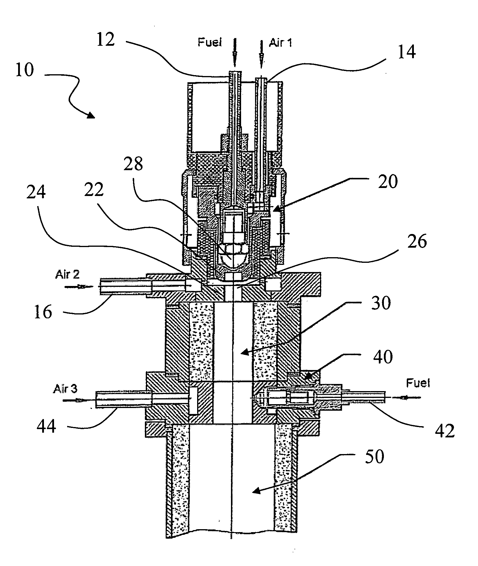
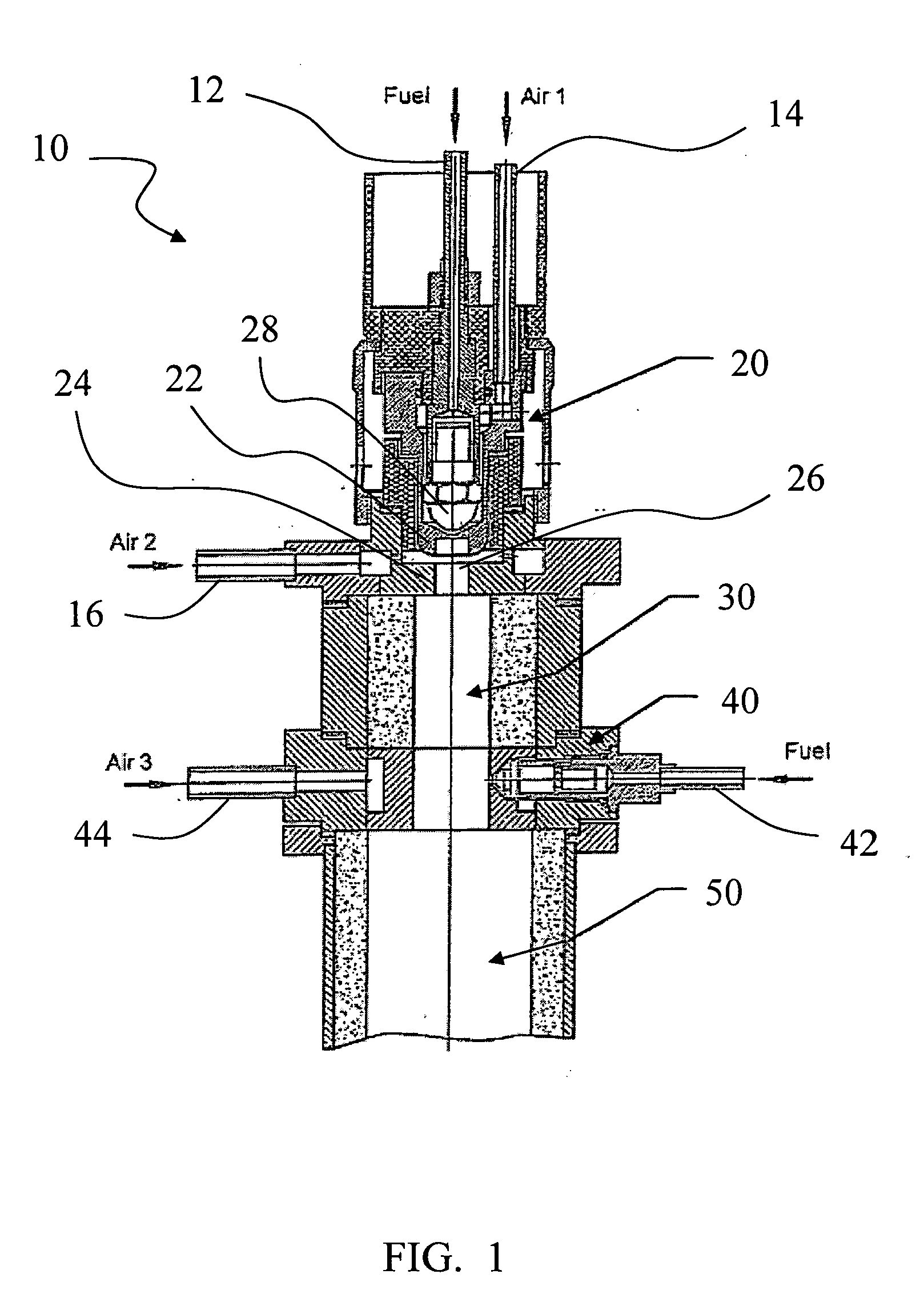
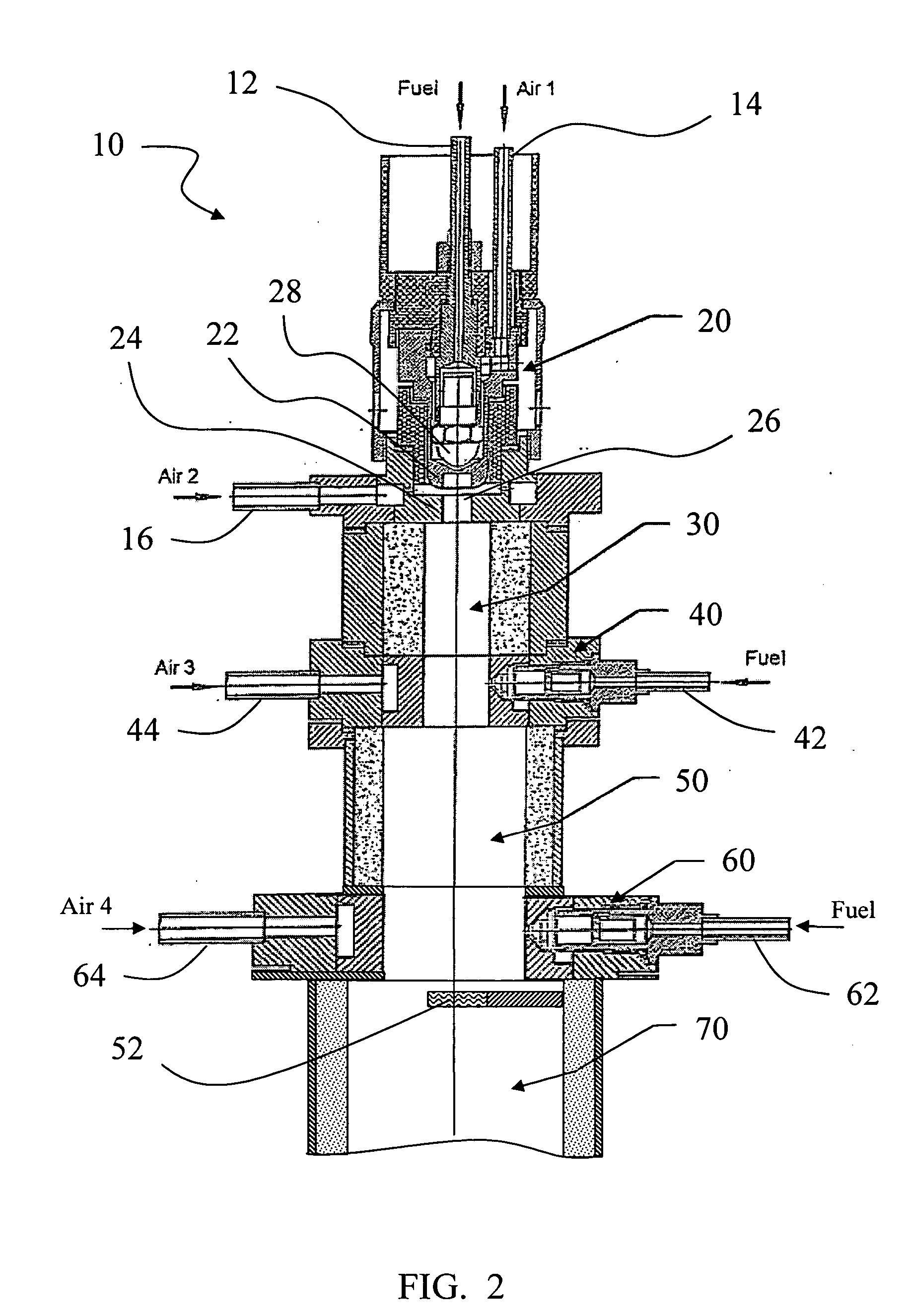
[0019] Robust, large volume plasma discharges are needed for fast start-up of low current, low electrical power plasmatron fuel reformers (“plasmatrons”) and for efficient operation after start-up. Using an appropriate electrode configuration, the rapid establishment, extinction and reestablishment of the plasma discharges, combined with initiation of persistent chemical reactions by the flux of active species generated by the discharge, result in a quasi-continuous plasma discharge. The quasi-continuous plasma discharge effectively fills the discharge region and initiates chemical reactions throughout that volume.

[0020] One application of plasmatrons involves partial oxidation of hydrocarbon fuels to produce hydrogen-rich fuels for use in internal combustion systems such as gasoline or diesel engines and their associated exhaust systems. Such plasmatrons may be selected for operation between stoichiometric partial oxidation and full combustion depending on conditions and applicati...


PUM


Abstract

A method and apparatus for a multistage plasmatron fuel reformer system having a wide dynamic operational range. In one aspect, the system includes a plasmatron configured for low flow operation followed by a reaction extension cylinder and then by a nozzle section capable of providing additional air and/or fuel inputs. The nozzle section is then followed by another reaction extension region. When high flow rate of the system is needed, the low fuel flow rate provided by the plasmatron followed by the first reaction extension region provides the high temperature used to effectively initiate the partial oxidation reaction in the next section. The initiation of this reaction may also be facilitated by the presence of hydrogen.

Description

FIELD OF THE INVENTION [0001] The present invention is directed to the field of fuel reforming and more particularly to a method and apparatus for a wide dynamic range multistage plasmatron reformer system. BACKGROUND OF THE INVENTION [0002] Plasmatron fuel converters or reformers (“plasmatrons”) reform hydrocarbons to generate a hydrogen rich gas which includes hydrogen and carbon monoxide through the use of plasma discharges. (See, for example, U.S. Pat. No. 6,322,757 to Cohn et al.; U.S. Pat. No. 5,887,554 to Cohn et al; U.S. Pat. No. 5,437,250 to Rabinovich et al; and U.S. Pat. No. 5,425,332 to Rabinovich et al.; and U.S. Patent Application Publication No. 2002 / 0012618 to Bromberg et al, the teachings of all of which are incorporated herein by reference). Plasmatron fuel conversion using low current, high voltage discharges can provide significant advantages. (For a general treatise on plasma physics, see J. Reece Roth, Industrial Plasma Engineering, Vol. 1 and 2, Institute of P...

Claims


Application Information

Patent Timeline
IPC IPC(8): B01J19/08C01B3/34H01M8/00H01M8/06
CPCB01J19/088B01J2219/0809B01J2219/0815B01J2219/0828B01J2219/083B01J2219/0854Y02E60/50B01J2219/0884B01J2219/0892B01J2219/0894C01B3/342C01B2203/0861H01M8/0612B01J2219/0869Y02P20/129
Inventor RABINOVICH, ALEXANDERALEXEEV, NIKOLAISAMOKHIN, ANDREIBROMBERG, LESLIECOHN, DANIEL R.HADIDI, KAMAL
Owner MASSACHUSETTS INST OF TECH
Why Eureka
Try Eureka