Light-emitting apparatus and illuminating apparatus

Inactive Publication Date: 2005-09-29
KYOCERA CORP
View PDF3 Cites 102 Cited by
  • Summary
  • Abstract
  • Description
  • Claims
  • Application Information

AI Technical Summary

Benefits of technology

[0042] According to the invention, the phosphors have an average grain diameter ranging 1 to 50 μm. In a case where the grain diameter is more than 50 μm, a rate that the fluorescent light emitted from the phosphors is interfered by the phosphors in the light transmitting member becomes larger, whereby the phosphors on their own becomes impediments to the light propagation. As a result, it becomes difficult for the fluorescent light to be put out to the outside of the light-emitting apparatus, and the light intensity is decreased in the light-emitting apparatus with ease.
[0043] On the other hand, in a case where the grain diameter is less than 1 μm, a probability that the light from light-emitting element propagating in the light transmitting member is absorbed in the phosphors becomes smaller, and the light from light-emitting element is put out to the outside with ease without undergoing wavelength conversion through between the phosphors. As a result, color variations in the light output from the light-emitting apparatus tend to become larger. Therefore, limiting the average grain diameter of the phosphors to a range of 1 to 50 μm prevents the decrease of light intensity and the large color variations in the output light.
[0044] According to the invention, the light-emitting element is designed to emit light exhibiting an emission spectrum having a peak wavelength at 450 nm or below. Moreover, the light transmitting member is made of silicone resin or fluorine resin. In this way, several advantages are gained: an undesirable decrease in the transmittance of the light transmitting member ascribable to the high-energy light of short wavelength emitted from the light-emitting element can be prevented effectively; an undesirable decrease in the strength of bonding between the light-emitting element and the base body can be prevented effectively; an undesirable decrease in the strength of bonding between the base body and the frame body can be prevented effectively; and the phosphors are able to allow conversion into light of varying colors, for example white-color light and blue-color light, etc.
[0045] According to the invention, a method for manufacturing the light-emitting apparatus comprises the steps of: attaching a frame body on a top surface of a base body having a placement portion for empl

Problems solved by technology

However, the conventional light-emitting apparatus shown in FIG. 8 poses the following problems.
As a result, the light emitted from the light-emitting element 104 is confined by the phosphors 106, which leads to an undesirable decrease in the light extraction efficiency (the efficiency of taking out the light emanating from the light-emitting layer of the light-emitting element 104).
This causes the upper phosphors 106 to interfere with propagation of light that has been wavelength-conver

Method used


Image

  • Light-emitting apparatus and illuminating apparatus
  • Light-emitting apparatus and illuminating apparatus
  • Light-emitting apparatus and illuminating apparatus

Examples


example 1

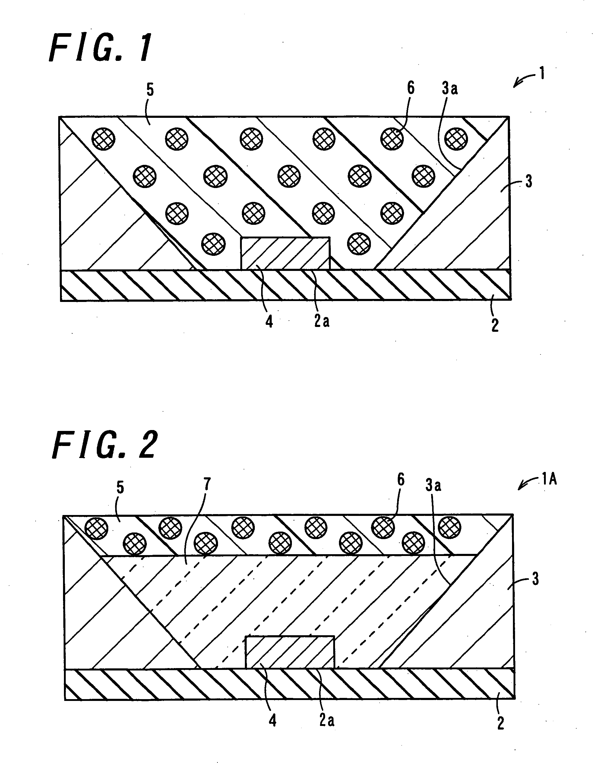
[0100] At first, as the base body 2, an alumina ceramics substrate was prepared for use.

[0101] The base body 2 is composed of a rectangular plate which is 3.5 mm in length×3.5 mm in width×0.5 mm in thickness. The base body 2 has, at the center of its top surface, the placement portion 2a for emplacing thereon the light emitting element 4. Moreover, in the base body 2, a wiring conductor composed of a W-made metallized wiring line is so disposed as to extend from the placement portion 2a to the under surface thereof.

[0102] Moreover, the frame body 3 was formed in the shape of a circular cylinder, the dimensions of which are: 3.5 mm in exterior diameter; 1.5 mm in height; 3.3 mm in diameter of upper opening; and 0.5 mm in diameter of lower opening.

[0103] Next, the 0.08 mm-thick light-emitting element 4 for emitting near-ultraviolet light was, at the Au—Sn bump disposed in its electrode, bonded to the wiring conductor. Concurrently, the frame body 3 was joined to the outer periphery...

example 2

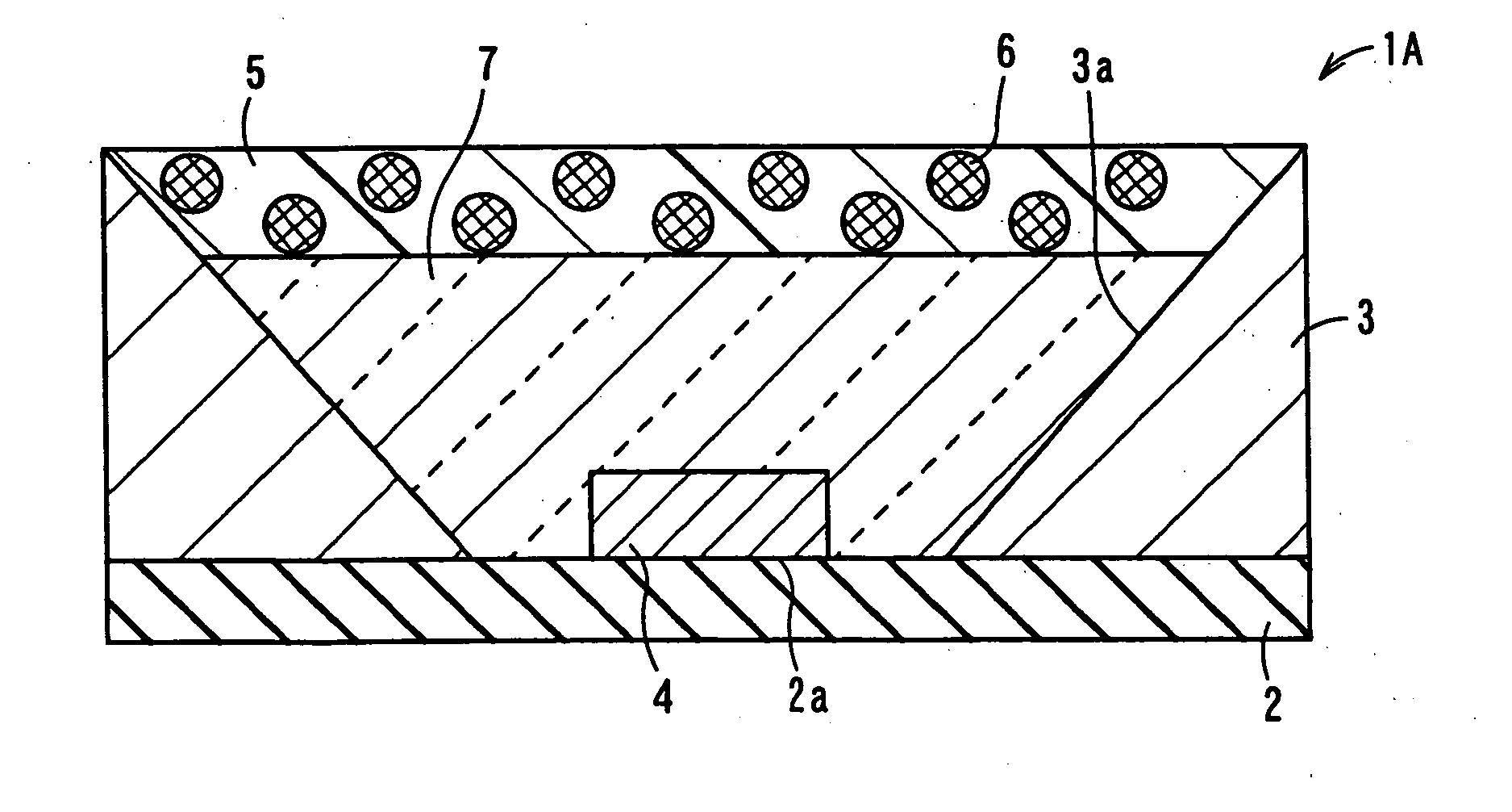
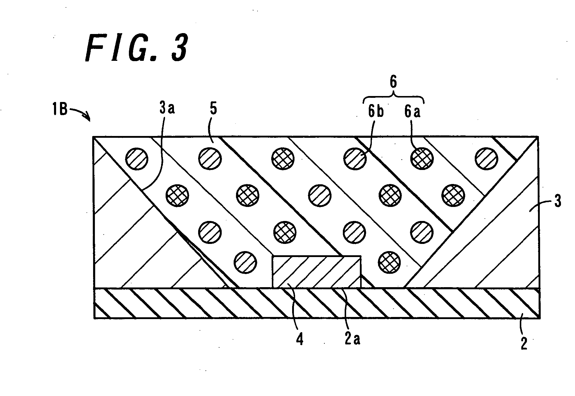
[0108] Hereinafter, a description will be given as to example of the light-emitting apparatus 1B of the invention with reference to FIG. 3.

[0109] In the example 2, components configuring the base body 2 and the frame body 3 in the light-emitting apparatus 1B are the same as those used in the example 1.

[0110] In the same way as the example 1, the phosphors 6 for red-color light emission (La2O2S:Eu) have a density of 5.8 g / cm3; those for green-color light emission (BaMgAl10O17:Eu) have a density of 3.8 g / cm3; and those for blue-color light emission (BaMgAl10O17:Eu, Mn) have a density of 3.8 g / cm3. These three different types of the phosphors 6 were blended together so as for the color temperature of light emitted from the light-emitting apparatus 1 to be 6500 K.

[0111] Moreover, as the light transmitting member 5, silicone resin materials of varying pre-cured viscosities, that is; 0.3; 0.4; 1.3; 10; 50; and 55 Pa.s were prepared for use. In each silicone resin material is admixed th...

example 3

[0115] In the example 3, components configuring the base body 2 and the frame body 3 in the light-emitting apparatus are the same as those used in the example 1.

[0116] The phosphors 6 for red-color light emission (La2O2:Eu) have a density of 5.8 g / cm3; those for green-color light emission ((BaMgAl)10O12:Eu, Mn) have a density of 3.8 g / cm3; and those for blue-color light emission ((Sr, Ca, Ba, Mg)10(PO4)6O12:Eu) have a density of 3.8 g / cm3. These three different types of the phosphors 6 were blended together.

[0117] Moreover, as the light transmitting member 5, silicone resin having pre-cured viscosities of 1.7 Pa.s is prepared for use. The silicone resin is vacuum-defoamed in a non-cured state by a vacuum defoamer. To the vacuum-defoamed silicone resin, admixed are the phosphors 6 admixed so as to put out desired visible light therein, so that a volume of the phosphors is 1 / 30, 1 / 24, 1 / 18, 1 / 15, 1 / 12, 1 / 6, 1 / 5 times as much as that of the silicone resin, respectively. In other word...


PUM


Abstract

There is provided a light-emitting apparatus with favorable radiation light intensity, which is excellent in light extraction efficiency, color temperature and color rendering property. The light-emitting apparatus includes a light-emitting element, a base body having, on its top surface, a placement portion for emplacing thereon the light-emitting element, a frame body attached to the top surface of the base body so as to surround the placement portion, a light transmitting member disposed inside the frame body so as to cover the light-emitting element, and phosphors contained in the light transmitting member, which performs wavelength conversion on the light emitted from the light-emitting element. The light transmitting member has a pre-cured viscosity ranging from 0.4 to 50 Pa.s.

Description

BACKGROUND OF THE INVENTION [0001] 1. Field of the Invention [0002] The present invention relates to a light-emitting apparatus and illuminating apparatus for radiating out light that has been emitted from a light-emitting element such as a light-emitting diode and then wavelength-converted by phosphors. [0003] 2. Description of the Related Art [0004]FIG. 8 is a sectional view showing a light-emitting apparatus 101 of conventional design for giving forth light of any given color using phosphors 106 which convert light such as near-ultraviolet light or blue-color light emitted from a light-emitting element 104 such as a light-emitting diode (LED) into red-color light, green-color light, blue-color light, yellow-color light or the like. In FIG. 8, the light-emitting apparatus 101 is mainly composed of a base body 102 made of an insulator; a frame body 103; a light transmitting member 105; and the light-emitting element 104. The base body 102 has, at the center of its top surface, a pl...

Claims


Application Information

Patent Timeline
IPC IPC(8): F21K99/00F21S2/00F21YH01L21/00H01L27/15H01L33/50H01L33/56
CPCH01L33/501H01L33/56H01L2924/0002H01L2924/00B27M1/003B27C5/00B27D5/00
Inventor MORI, YUKIMIYAKE, AKIRA
Owner KYOCERA CORP
Why Eureka
Try Eureka