
Biomagnetic measurement apparatus and method for setting horizontal position for biomagnetic measurement

a biomagnetic measurement and horizontal position technology, applied in the direction of patient positioning for diagnostics, magnetic field measurement using superconductive devices, instruments, etc., can solve the problem of a lot of measurement time, and achieve the effect of simple configuration and simple configuration

Inactive Publication Date: 2005-09-29
HITACHI HIGH-TECH CORP
View PDF5 Cites 13 Cited by
  • Summary
  • Abstract
  • Description
  • Claims
  • Application Information

AI Technical Summary

Benefits of technology

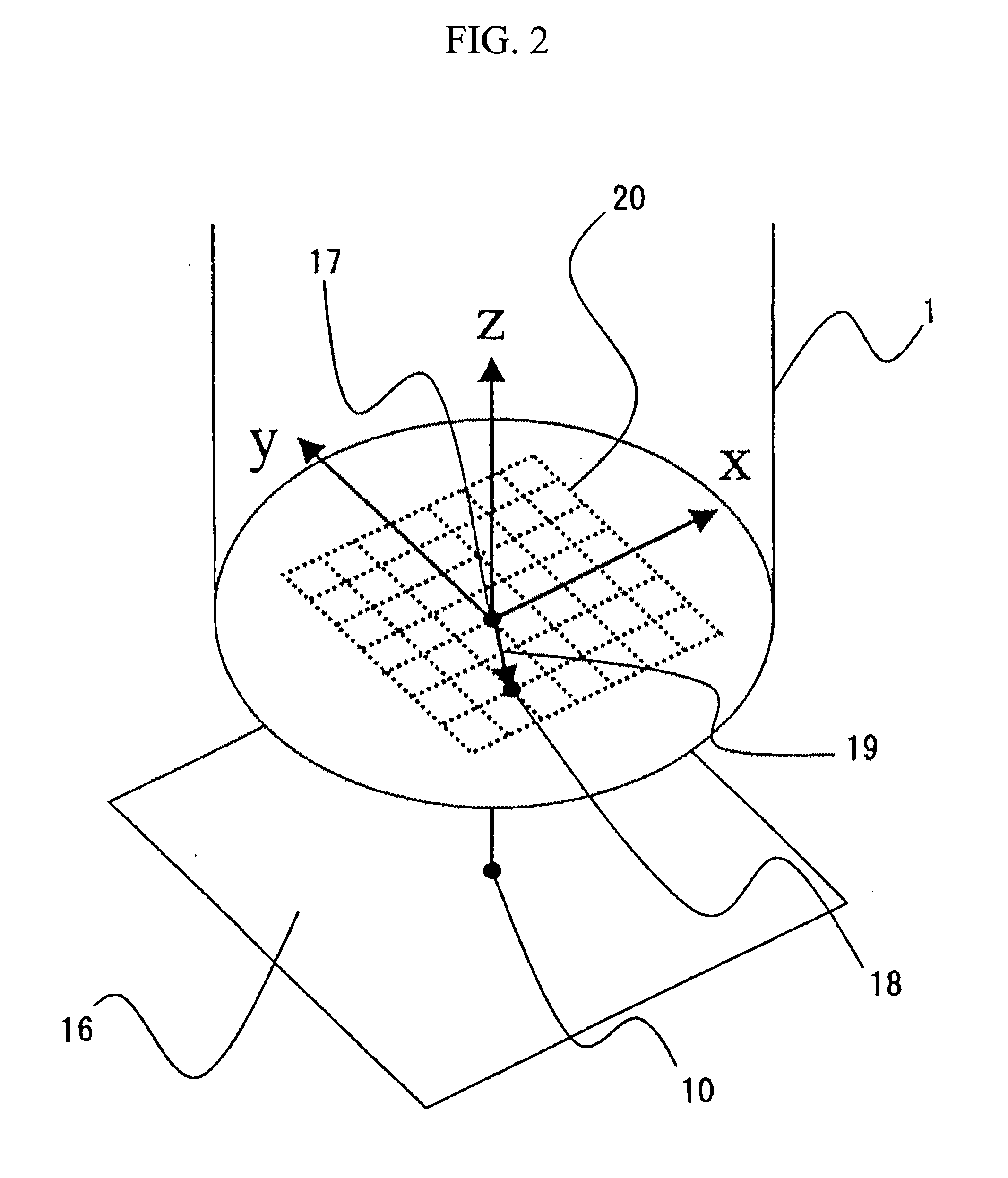
The present invention provides a biomagnetic measurement apparatus and method that can simultaneously adjust the position of a subject and calibrate the magnetic sensor in a simple and efficient manner. The apparatus includes a SQUID magnetometer for measuring the magnetic field generated from the subject's heart, a marker with a known magnetic field strength attached to the subject, and a computing system that calculates the position of the marker in the depth direction based on the magnetic field strength and the distance between the marker and the SQUID magnetometer. The apparatus can be easily attached to the subject and can be calibrated in a short time. The invention simplifies the positional adjustment and magnetic sensor calibration process, making the biomagnetic measurement apparatus more efficient and user-friendly.

Problems solved by technology

In a conventional biomagnetic measurement apparatus, it is necessary to separately conduct the grasp of positional relationship between a subject and a magnetic field sensor and the calibration of the strength of a magnetic field in a depth direction, so that measurement requires a lot of time.

Method used


Image

  • Biomagnetic measurement apparatus and method for setting horizontal position for biomagnetic measurement
  • Biomagnetic measurement apparatus and method for setting horizontal position for biomagnetic measurement
  • Biomagnetic measurement apparatus and method for setting horizontal position for biomagnetic measurement

Examples


embodiment 1

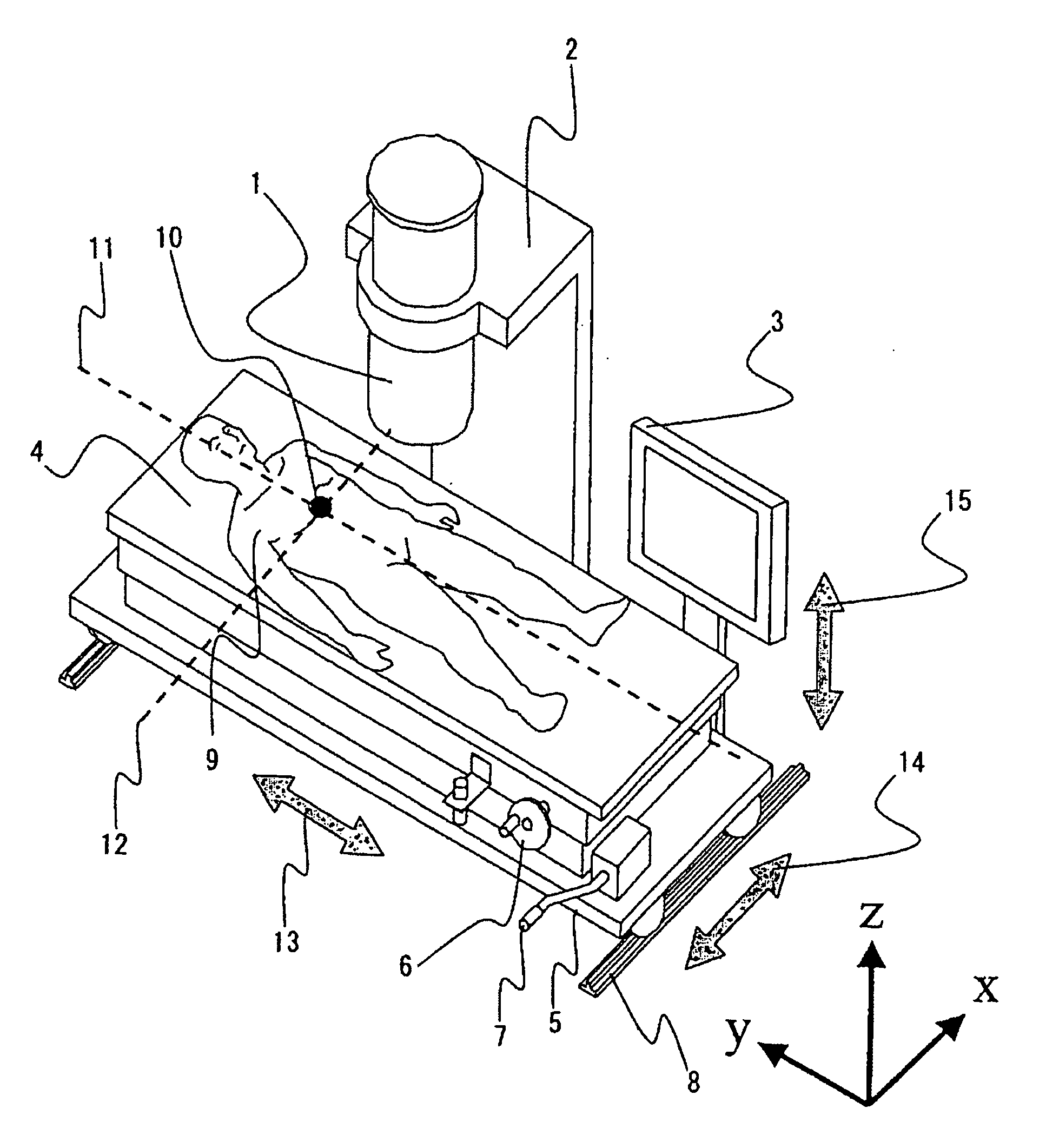
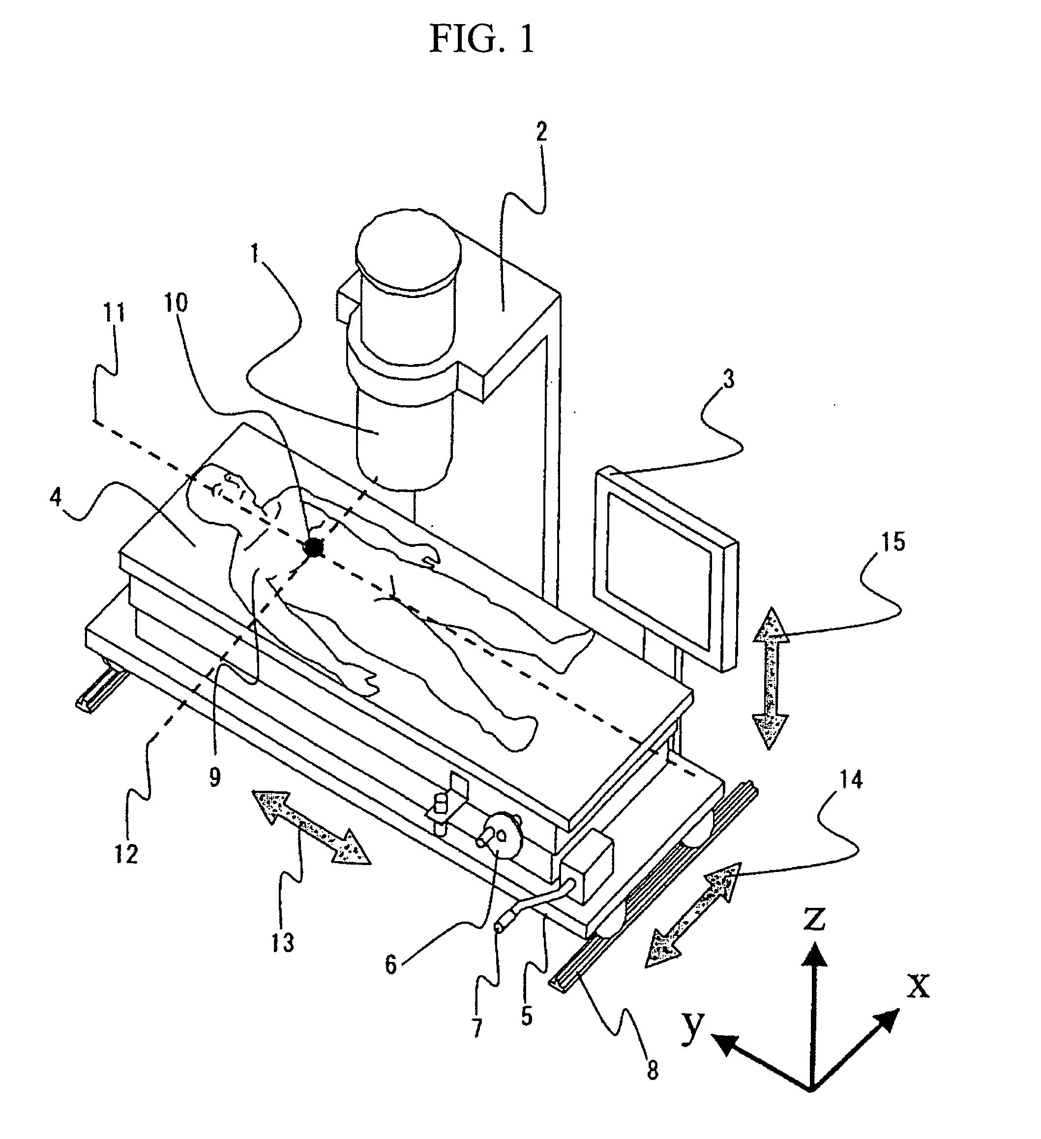
[0039] As shown in FIG. 1, the biomagnetic measurement apparatus according to the present invention comprises a cryogenic container 1 for cooling SQUID magnetometers, a gantry 2 for fixing the position of the cryogenic container 1, a monitor 3 for displaying information on the positional adjustment of an object, an inspection bed 4 and a holding stand 5 for holding the bed 4.

[0040] The gantry 2 for holding the cryogenic container 1 is fixed on a floor surface. The distance between the bottom face of the cryogenic container 1 and the floor surface is represented by a known value set in advance, and the bottom face of the cryogenic container 1 is in a position fixed with respect to the floor surface. The bottom face of the cryogenic container 1 and the top face of the bed are disposed in an almost parallel manner with respect to the floor surface.

[0041] The gantry 2 for holding the cryogenic container 1 is fixed on the floor surface and the bottom face of the cryogenic container 1 m...

embodiment 2

[0055] The marker including the permanent magnet is attached to the xiphoid process portion of the subject and a form image including the pectoral region is obtained via a three-dimensional X-ray CT apparatus. The marker is shown in an X-ray CT cross-sectional image on a CT image. Then, the subject is measured via the biomagnetic measurement apparatus according to Embodiment 1 regarding the change of the magnetic field strength, and a functional image is obtained (showing an isofield contour map, a current-arrow map, an isofield-integral map, and functional information on cardiac activity in an estimated position of an activated region (current source), for example). Since the position of the heart of the subject is not clear with the functional image obtained by the biomagnetic measurement apparatus, the form image including the pectoral region obtained by the X-ray CT apparatus and the functional image obtained by the biomagnetic measurement apparatus are superposed, thereby obtai...


PUM


Abstract

A biomagnetic measurement apparatus that readily enables the positional adjustment of a test object in biomagnetic measurement and a biomagnetic measurement method are provided. In biomagnetic measurement, in the case where the test object is a heart, for example, a permanent magnet is disposed on the body surface of the xiphoid process of a subject and the pectoral region is disposed under the bottom face of the cryogenic container. A processing unit stores the calibration curve of the permanent magnet and performs a process for estimating the positional relationship between the subject and the bottom face of the cryogenic container in accordance with the measurement result of the magnetic field strength of the permanent magnet. Also, the processing unit performs a process for estimating the distance between the body surface of the test object and the bottom face of the cryogenic container.

Description

CLAIM OF PRIORITY [0001] The present application claims priority from Japanese application JP 2004-90803 filed on Mar. 26, 2004, the content of which is hereby incorporated by reference into this application. BACKGROUND OF THE INVENTION [0002] 1. Field of the Invention [0003] The present invention relates to a biomagnetic measurement apparatus that measures a faint magnetic field (magnetism) emitted from the brain or the heart, for example, of a living body by using a SQUID (Superconducting Quantum Interference Device) magnetometer, which is a superconducting device. Especially, the present invention relates to a biomagnetic measurement apparatus that is capable of readily adjusting the position of a subject and the position of the magnetometer, and correcting data. [0004] 2. Background Art [0005] In a biomagnetic measurement apparatus, it is difficult to accurately grasp the positional relationship between a subject and magnetic field sensors, since a SQUID magnetometer is disposed...

Claims


Application Information

Patent Timeline
Patent Type & Authority Applications(United States)
IPC IPC(8): A61B5/04G01R33/035A61B5/05G01R33/02G01V15/00
CPCA61B5/04007G01V15/00A61B6/04A61B5/243
Inventor WATANABE, ATSUSHIMURAKAMI, MASAHIROTESHIGAWARA, KENJIMATSUOKA, YOSHIO
Owner HITACHI HIGH-TECH CORP
Learn More