
IPS mode liquid crystal display

a liquid crystal display and liquid crystal technology, applied in static indicating devices, instruments, non-linear optics, etc., can solve the problems of narrow viewing angle, narrow viewing angle, difficult to obtain perfect display of black color, etc., and achieve the effect of high contrast ratio and better view

Active Publication Date: 2005-09-29
NITTO DENKO CORP
View PDF8 Cites 21 Cited by
  • Summary
  • Abstract
  • Description
  • Claims
  • Application Information

AI Technical Summary

Benefits of technology

The present invention relates to an IPS mode liquid crystal display that uses an optical film with a polarizing plate and a retardation film to achieve a high contrast ratio and improved viewing angle. The optical film is made by laminating a polarizing plate and a retardation film together. The invention provides an optical film that can cancel light leakage in a direction deviated from the optical axis with specific retardation films, resulting in a better view with a wide viewing angle. The optical film is made with a transparent protective film on each surface of the polarizing plate, and the refractive indexes and film thickness of the protective films are optimized to achieve the desired optical properties. The invention also provides an IPS mode liquid crystal display that uses this optical film to achieve a high contrast ratio and improved viewing angle.

Problems solved by technology

However, in TN mode, even when black view is displayed, optical leakage resulting from birefringence caused by liquid crystal molecule near a substrate made it difficult to obtain perfect display of black color owing to driving characteristics thereof.
However, although almost perfect black view may be realized in normal direction to a panel in IPS mode, when a panel is observed in oblique direction, inevitable optical leakage occurs caused by characteristics of a polarizing plate in a direction shifted from an optical axis of the polarizing plates placed on upper and lower sides of the liquid crystal cell, as a result, leading to a problem of narrowing of a viewing angle.
That is, a polarizing plate using a triacetyl cellulose (TAC) film generally employed, as a protective film, has had a problem that a viewing angle is narrowed by birefringence that the TAC film has.
With retardation films described in the above-mentioned documents, however, it is difficult to realize a sufficiently wide viewing angle of an IPS mode liquid crystal display.

Method used


Image

  • IPS mode liquid crystal display
  • IPS mode liquid crystal display
  • IPS mode liquid crystal display

Examples


example 1

(Preparation of Polarizing Plate)

[0107] Triacetyl cellulose (TAC) films (transparent protective films each with a thickness of 80 μm) were laminated with an adhesive on both surfaces of a film (polarizer having a thickness of 20 μm) obtained by causing iodine to adsorb into a polyvinyl alcohol-based film and then stretching the film. The TAC film had an in-plane retardation Re of 4 nm and a thickness direction retardation Rth of 50 nm.

(Optical Film (F1))

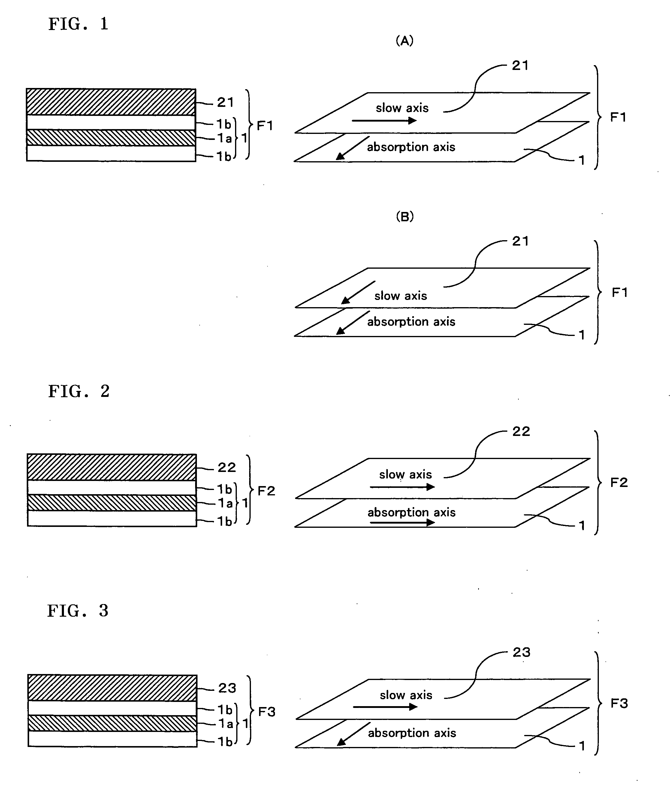
[0108] A polycarbonate film was stretched to thereby obtain a retardation film having a thickness of 50 μm, an in-plane retardation Re1 of 260 nm and an Nz of 0.5. The retardation film and the polarizing plate were laminated one the other with a pressure sensitive adhesive so that the slow axis of the retardation film and the absorption axis of the polarizing plate are parallel to each other to thereby prepares of an optical film (F1).

(Optical Film (F2))

[0109] A norbornene-based film was stretched to thereby obtain a retardat...

example 2

(Optical Film (F2))

[0112] A film (Pure Ace WR, manufactured by TEIJIN CHEMICALS LTD.) satisfying a relation of {Δnd(450 nm) / Δnd(550 nm)}2 of 220 nm and an Nz of 1.0. The retardation film and the polarizing plate similar to that used in Example 1 were laminated together so that the slow axis of the retardation film and the absorption axis of the polarizing plate are parallel to each other with a pressure sensitive adhesive to thereby obtain an optical film (F2).

(Liquid Crystal Display)

[0113] A liquid crystal display was fabricated in a similar way to that in Example 1 with the exception that in Example 1, the optical film (F2) obtained in Example 2 was employed.

(Evaluation)

[0114] The liquid crystal display was placed on the backlight to measure a contrast ratio in a direction of gradient to make 70 degree from normal direction was measured in a direction to make an angle of 45 degrees to relative to the optical axis of the polarizing plates with the absorption axes thereof pe...

example 3

(Liquid Crystal Display)

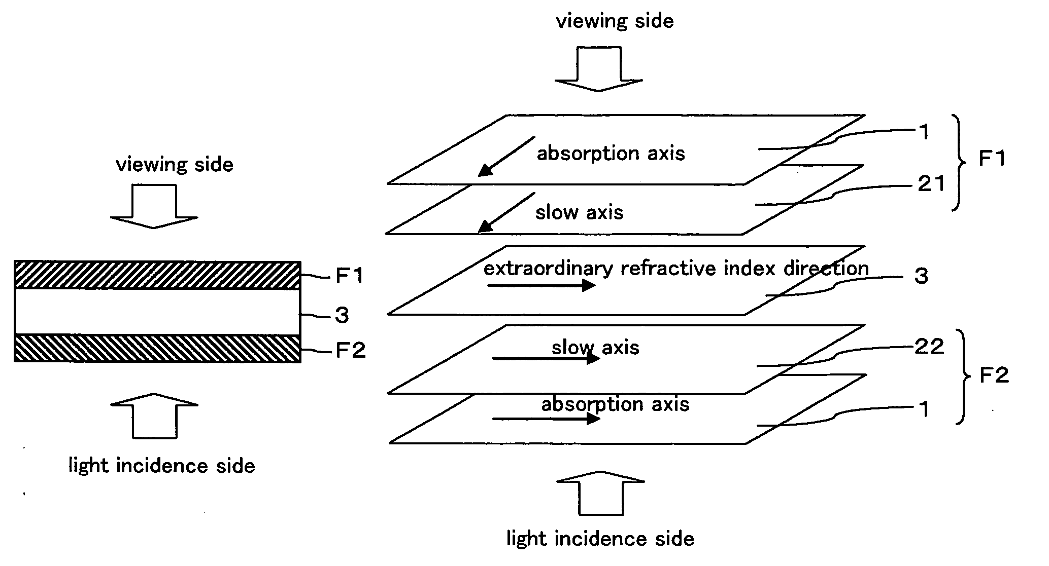
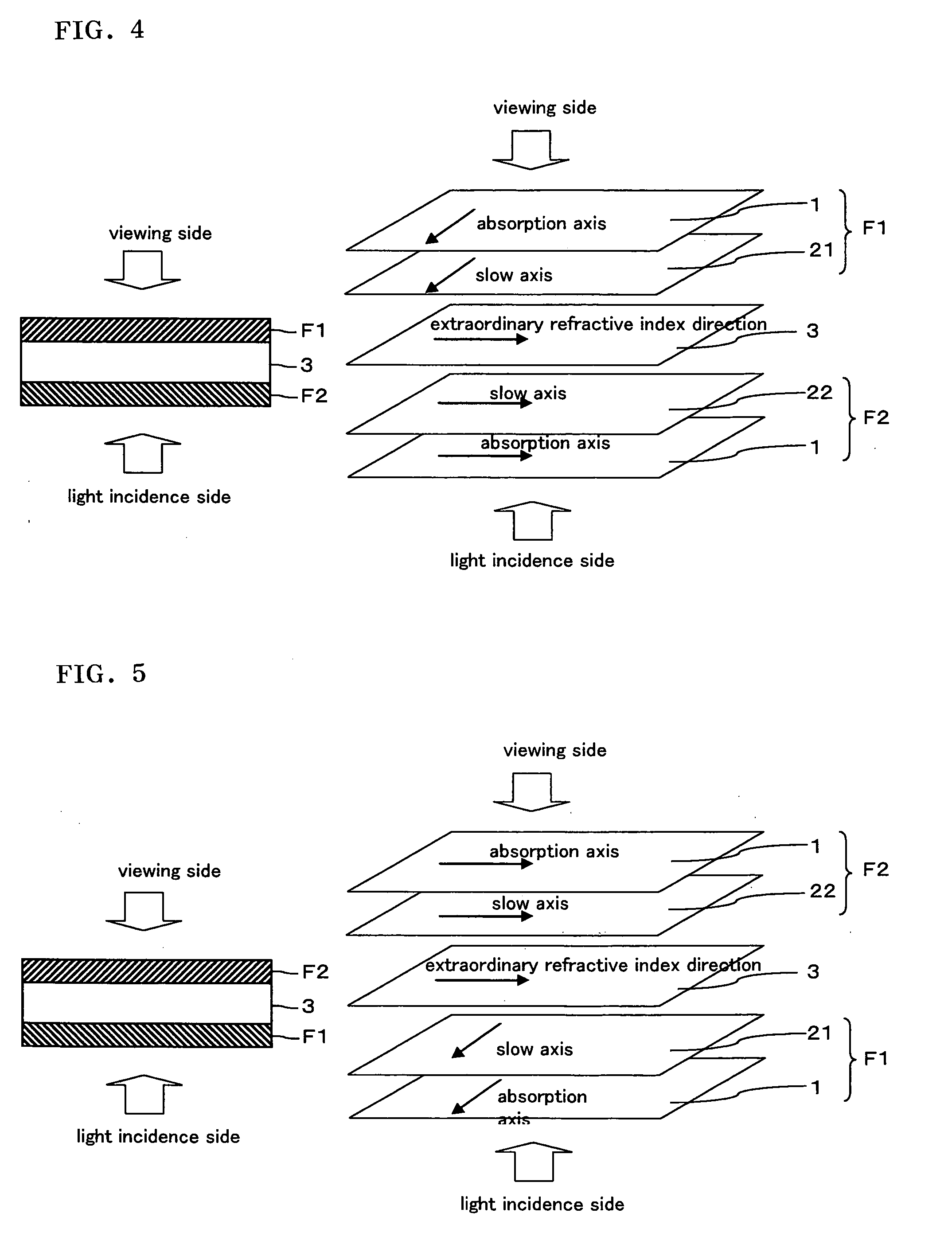
[0115] The optical film (F1) and the optical film (F2) obtained above in Example 1 were employed. A liquid crystal in IPS mode having a retardation value of 310 nm for wavelength of 550 nm was employed and, as shown in FIG. 5, the optical films (F2) and (F1) were laminated, respectively, on the cell substrate on the viewing side and the cell substrate on the light incidence side. The retardation film sides of the optical films (F1) and (F2) faced the liquid crystal cell. In this case, the absorption axis of the polarizing plate of the optical film (F1) and an extraordinary refractive index direction of a liquid crystal in the liquid crystal cell were perpendicular to each other. The optical film (F1) and the optical film (F2) were disposed as shown in FIG. 5.

(Evaluation)

[0116] The liquid crystal display was placed on the backlight to measure a contrast ratio in a direction of gradient to make 70 degree from normal direction was measured in a direction to...


PUM

PropertyMeasurementUnit
thickness direction retardationaaaaaaaaaa
wavelengthaaaaaaaaaa

Abstract

An IPS mode liquid crystal display comprising a liquid crystal cell, an optical film (F1) provided on a cell substrate on one side of the liquid crystal cell and comprises a polarizing plate comprising a transparent protective film having an in-plane retardation Re 10 nm or less and a thickness direction retardation Rth in the range of from 30 to 100 nm, a retardation film having an Nz value in the range of from 0.3 to 0.7 and an in-plane retardation Re1 in the range of from 200 to 300 nm, and an optical film (F2) provided on a cell substrate on the other side of the liquid crystal cell and comprises the polarizing plate and a retardation film having an Nz value in the range of from 0.9 to 1.2 and an in-plane retardation Re2 in the range of from 150 to 280 nm, and the absorption axes of the polarizing plates of the optical film (F1) and the optical film (F2) are perpendicular to each other, and both films are disposed so that the retardation film sides face the liquid crystal cell. The IPS mode liquid crystal display has a high contrast ratio across a wide range, and capable of realizing a better view.

Description

BACKGROUND OF THE INVENTION [0001] 1. Field of the Invention [0002] This invention relates to an IPS mode liquid crystal display using an optical film obtained by laminating a polarizing plate with retardation film, and operating in an IPS mode. [0003] 2. Description of the Background Art [0004] Conventionally, as a liquid crystal display, there has been used a liquid crystal display in TN mode in which a liquid crystal having a positive dielectric anisotropy is twisted aligned between substrates mutually facing to each other. However, in TN mode, even when black view is displayed, optical leakage resulting from birefringence caused by liquid crystal molecule near a substrate made it difficult to obtain perfect display of black color owing to driving characteristics thereof. On the other hand, in a liquid crystal display in IPS mode, since liquid crystal molecule has almost parallel and homogeneous alignment to a substrate surface in non-driven state, light passes through the liquid...

Claims


Application Information

Patent Timeline
Patent Type & Authority Applications(United States)
IPC IPC(8): G02F1/133G02F1/1335G02F1/13363G02F1/1343
CPCG02F1/13363G02F1/134363G02F2413/02G02F2202/40G02F2001/133635G02F1/133635G02F1/1335
Inventor YANO, SHUUJIKAWAI, MASAYUKI
Owner NITTO DENKO CORP
Learn More