
Method of apparatus for detecting particles on a specimen

a technology of apparatus and specimen, which is applied in the direction of optically investigating flaws/contamination, semiconductor/solid-state device testing/measurement, instruments, etc., can solve the problems of display element not being given to a constitution capable, inability to use display elements, and inability to detect particles on specimens, etc., to reduce diffracted light, high accuracy, and high speed

Inactive Publication Date: 2005-09-29
HITACHI HIGH-TECH CORP
View PDF6 Cites 33 Cited by
  • Summary
  • Abstract
  • Description
  • Claims
  • Application Information

AI Technical Summary

Benefits of technology

[0016] According to the invention, it is possible to achieve an effect of reducing the diffracted light from a circuit pattern on a board of an LSI pattern or the like and of detecting a small particle or defect of the 0.1 μm level, a particle or a defect shortcircuiting wirings, or a particle having the shape of a thin film at high speed and with high accuracy for a board constituting an inspected object that has a transparent film in the form of an oxide film or the like formed at a surface thereof and on which a repeated pattern and a nonrepeated pattern are mixed.

Problems solved by technology

In a step of fabricating a semiconductor device, when a particle is present on a semiconductor board (wafer), the particle may constitute the cause of an insulation failure or a shortcircuit of the wiring.
Further, in accordance with the demand for miniaturization of a semiconductor element, a fine particle also constitutes a cause of an insulation failure of a capacitor or the destruction of a gate oxide film.
Similarly, also in a step of fabricating a liquid crystal display element, when a particle is mixed on a pattern or some defect is produced, the display element cannot be used.
The situation stays the same also in a step of fabricating a printed board, and a shortcircuit of a pattern or a failure in a connection may be caused by such a particle.
However, according to the techniques proposed in the above-cited publications, consideration is not given to a constitution capable of detecting a fine particle or a defect, on a board on which a repeated pattern are mixed, and a nonrepeated pattern with high sensitivity and at high speed.
Further, according to the technologies disclosed in the above-described publications, consideration is not given to a constitution capable of promoting a good sensitivity in detecting a small particle or a defect at the 0.1 μm level in a region having a high pattern density.
Further, according to the technologies disclosed in the above-described publications, consideration is not given to a constitution capable of promoting a good sensitivity in detecting a particle or a defect that produces a shortcircuiting of wirings or a good sensitivity in detecting a particle in the shape of a thin film.
Further, according to the technology disclosed in JP-A-2001-60607, consideration is not given to a constitution capable of promoting an increased accuracy in the measurement of a particle or a defect.
Further, according to the technology disclosed in JP-A-2001-60607, consideration is not given to a constitution capable of promoting a good sensitivity in detecting a particle on a surface of a wafer formed with a transparent thin film.

Method used


Image

  • Method of apparatus for detecting particles on a specimen
  • Method of apparatus for detecting particles on a specimen
  • Method of apparatus for detecting particles on a specimen

Examples


Embodiment Construction

[0032] An explanation will be given of an embodiment according to the present invention with reference to the drawings.

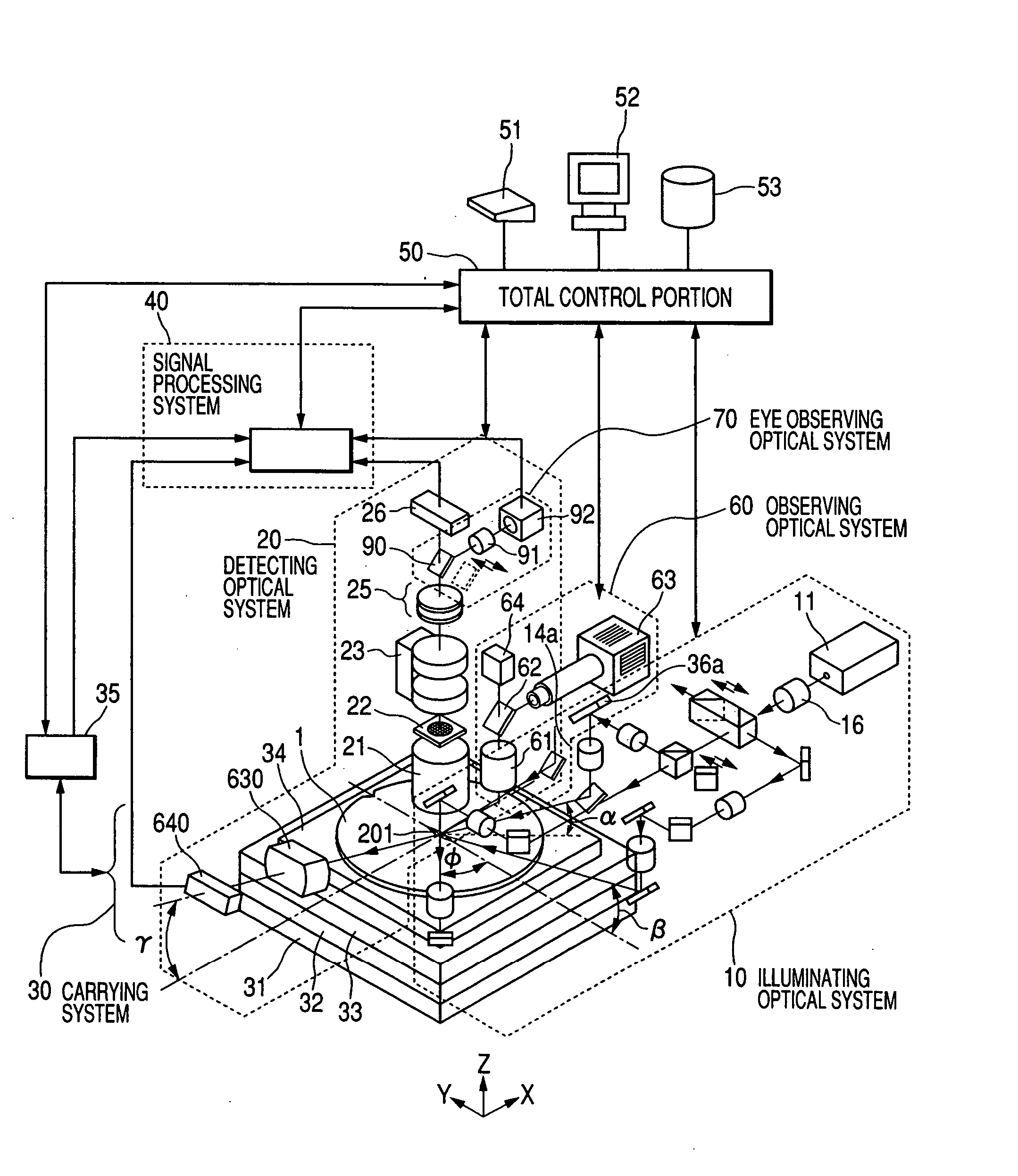
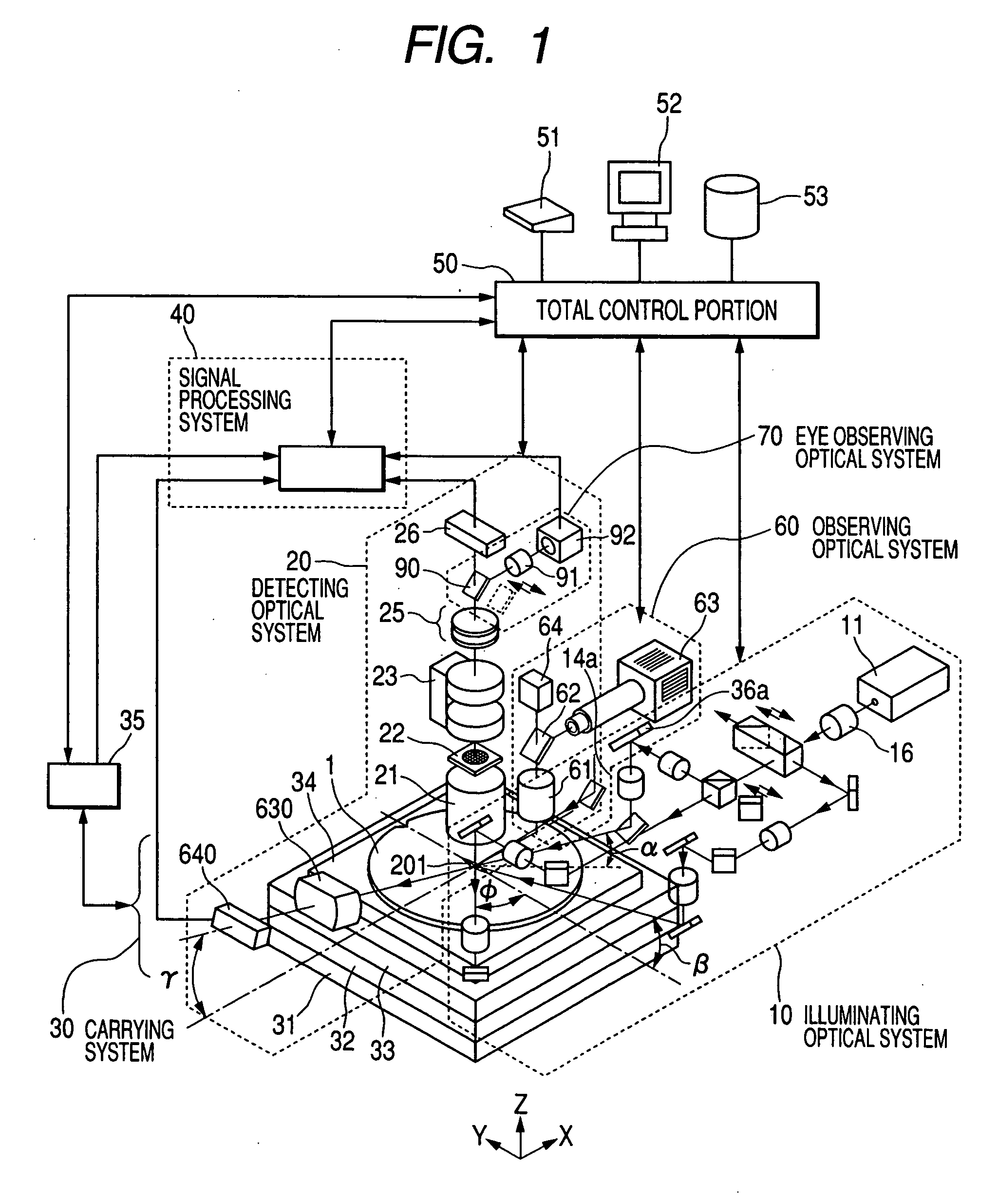
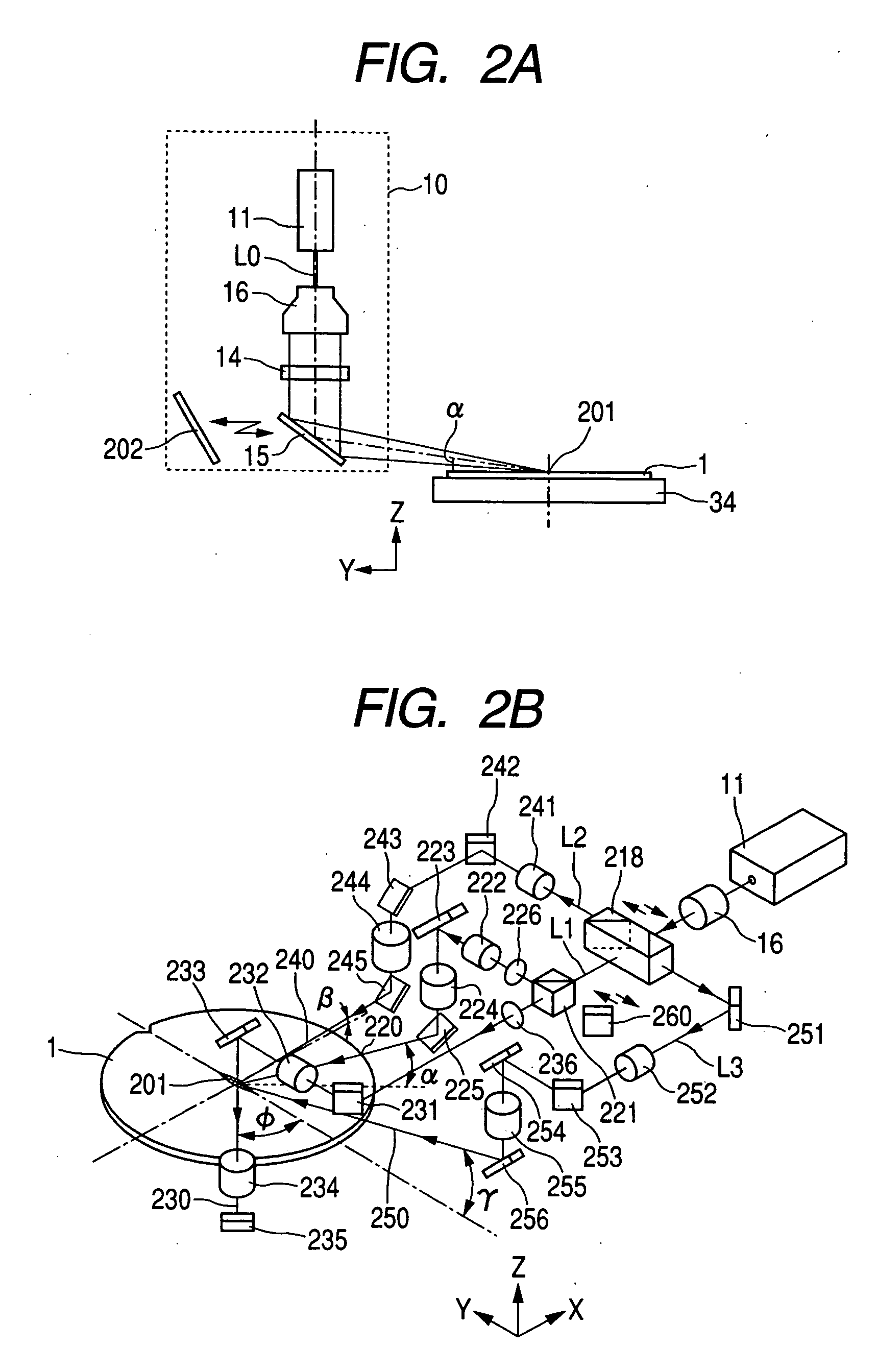
[0033] A defect inspecting apparatus according to the invention makes it possible to inspect a product for a defect, such as a particle on a detected board of a wafer or the like, and for various defects which constitute a pattern defect, a micro scratch and the like, in various kinds of product and various fabricating steps, with high sensitivity and at high speed, particularly to detect a defect on a surface of a thin film formed on a surface of a wafer by separating the defect from a defect in the thin film. For that purpose, in a defect inspecting apparatus according to the invention, as shown in FIG. 1, an angle α of irradiating and a direction φ of irradiating a slit-like beam 201, which is illuminated by an illuminating optical system 10, are made to be variable in accordance with the object being inspected, a detecting optical system 20 is installed to cons...


PUM

PropertyMeasurementUnit
widthaaaaaaaaaa
wavelengthaaaaaaaaaa
optical imageaaaaaaaaaa

Abstract

An apparatus for inspecting a pattern to detect a small pattern defect has an illuminating light source, as illuminating optical system having a plurality of illuminating portions for switching an optical path of illuminating light flux to a surface of board constituting the inspected object from a plurality of directions different from each other, a detecting optical system having a variable magnification using an object lens for condensing reflected diffracted light from the illuminated board, a focusing optical system having a variable magnification capable of focusing an optical image by converged reflected diffracted light with a desired focusing magnification and an optical detector for detecting the optical image focused by the focusing optical system to convert it into an image signal, an A / D converter for converting the image signal into a digital image signal, and an image signal processor for processing the digital image signal to detect the defect.

Description

BACKGROUND OF THE INVENTION [0001] The present invention relates to a method and apparatus for detecting a particle present on a thin film board, a semiconductor board or a photomask in the process of fabricating a semiconductor chip or a liquid crystal product. The present invention also relates to a method and apparatus for detecting a defect produced at a circuit pattern and inspecting the situation which may have caused production of a particle or a defect in a step of fabricating a device which is subjected to a measurement by analyzing the detected particle or defect. [0002] In a step of fabricating a semiconductor device, when a particle is present on a semiconductor board (wafer), the particle may constitute the cause of an insulation failure or a shortcircuit of the wiring. Further, in accordance with the demand for miniaturization of a semiconductor element, a fine particle also constitutes a cause of an insulation failure of a capacitor or the destruction of a gate oxide ...

Claims


Application Information

Patent Timeline
Patent Type & Authority Applications(United States)
IPC IPC(8): G01N21/88G01N21/956H01L21/66
CPCG01N21/956
Inventor HAMAMATSU, AKIRANOGUCHI, MINORIOHSHIMA, YOSHIMASAUTO, SACHIOUENO, TAKETONAKANO, HIROYUKIJINGU, TAKAHIROHATANO, HISASHIMOHARA, YUKIHISAOTANI, SEIJITOGASHI, TAKAHIRO
Owner HITACHI HIGH-TECH CORP
Learn More