Control of pressurized microchannel processes

a microchannel and process technology, applied in process and machine control, machine/engine, chemical production, etc., can solve the problems of increasing complexity, affecting the operation of the device, and reducing so as to increase the concentration of low-thermal energy density materials and reduce the proportion of diluen

Inactive Publication Date: 2005-09-29
VELOCYS CORPORATION
View PDF21 Cites 3 Cited by
  • Summary
  • Abstract
  • Description
  • Claims
  • Application Information

AI Technical Summary

Benefits of technology

[0011] In a preferred embodiment, the method further includes the steps of providing a catalyst within the first process unit, providing a second multi-planar microchannel process unit, the second multi-planar microchannel process unit at least partially contained within the containment vessel, establishing a second containment vessel pressure within the containment vessel, checking for leaks from the containment vessel, initiating a first unit operation within the first process unit, initiating a second unit operation within the second process unit, and maintaining a differential between a containment vessel pressure and a first multi-planar microchannel process unit pressure, and, optionally, between the containment vessel pressure and a second multi-planar micro

Problems solved by technology

Unlike a tubular reactor, a multi-planar device does not easily handle such pressures at the temperatures required.
In addition to the structural integrity issues raised by planar elements and laminations and the temperature and pressure issues noted above, thin walls to reduce weight and improve heat transfer add further complexity.
This is

Method used


Image

  • Control of pressurized microchannel processes
  • Control of pressurized microchannel processes
  • Control of pressurized microchannel processes

Examples


Embodiment Construction

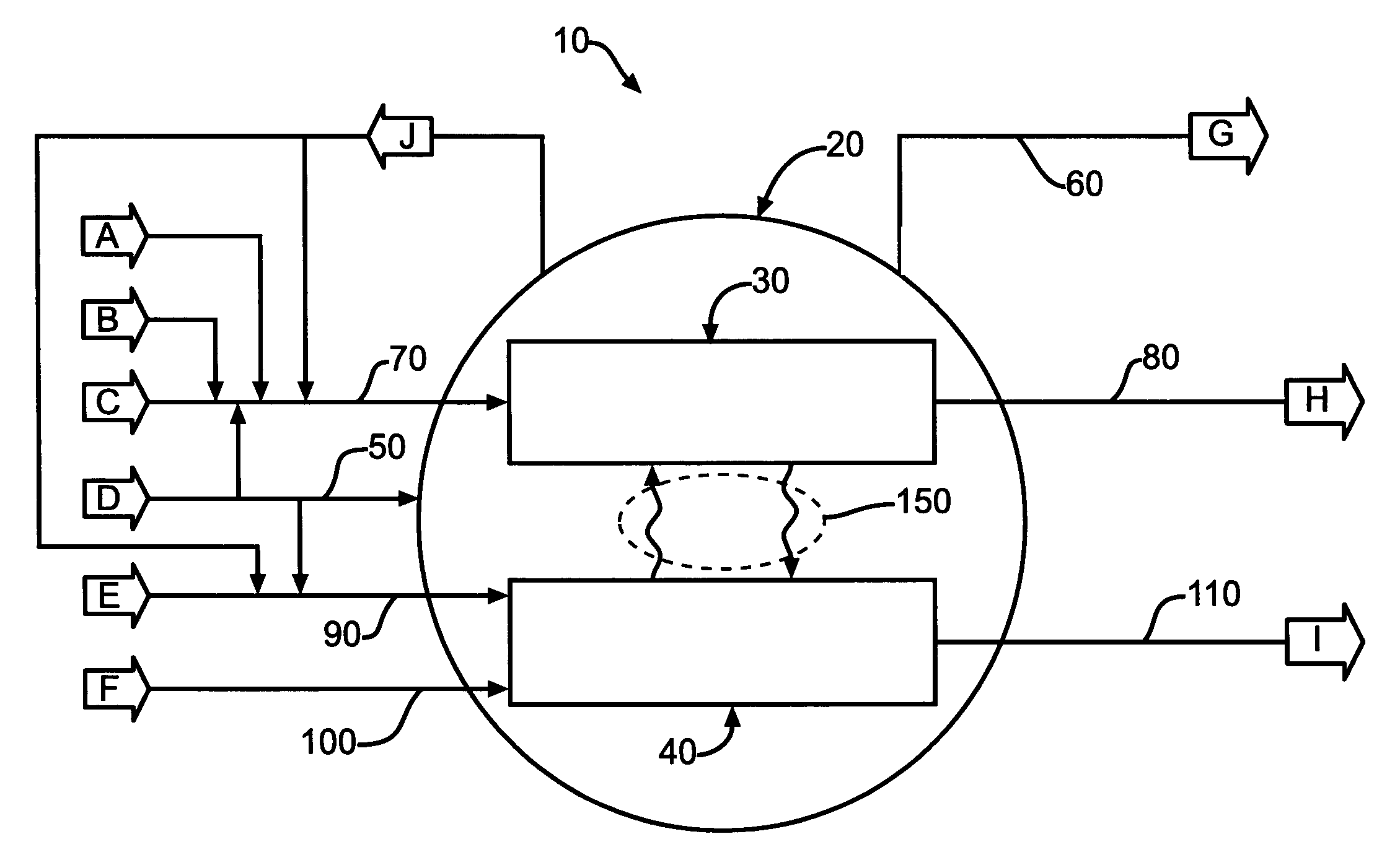
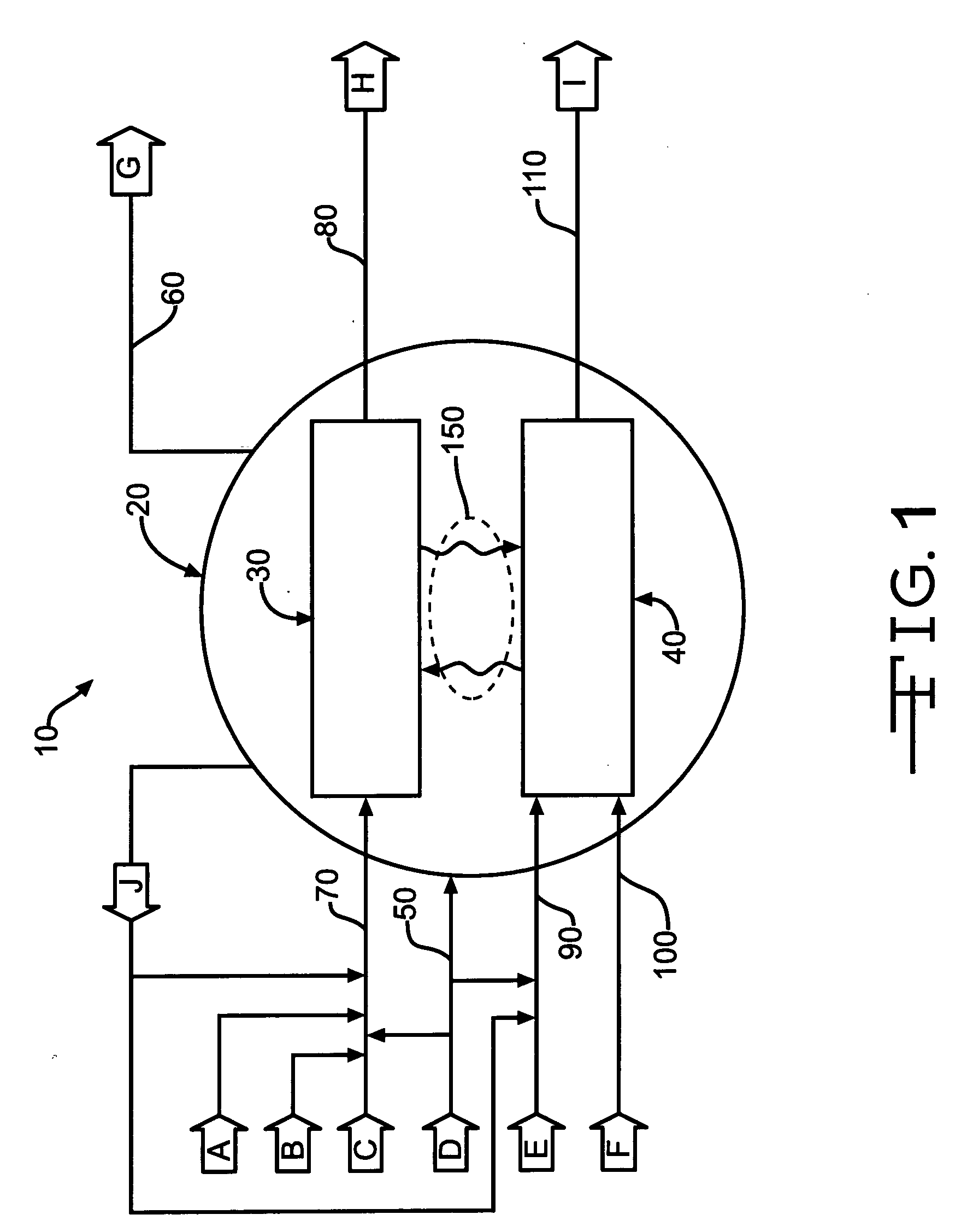
[0020] The following reference indicators are provided as an aid to an understanding of the figures: [0021]10 microchannel process [0022]20 containment vessel [0023]30 first microchannel process unit [0024]40 second microchannel process unit [0025]50 containment vessel inlet [0026]60 containment vessel vent [0027]70 first microchannel process unit inlet [0028]80 first microchannel process unit outlet [0029]90 first process unit inlet to second microchannel process unit [0030]100 second process unit inlet to second microchannel process unit [0031]110 second microchannel process unit outlet [0032]150 process unit—process unit heat transfer [0033] A first reactant material [0034] B first catalyst activation material [0035] C second reactant material [0036] D pressurizing material [0037] E third reactant material [0038] F fourth reactant material [0039] G vented / flared material [0040] H first products material [0041] I second products material [0042] J purge material

[0043] Reference to...


PUM

PropertyMeasurementUnit
Timeaaaaaaaaaa
Pressureaaaaaaaaaa
Timeaaaaaaaaaa

Abstract

A method of starting up and shutting down a microchannel process is provided. Included are the steps of providing a first multi-planar process unit, preferably adapted to process an endothermic reaction, a second multi-planar process unit, preferably adapted to process an exothermic reaction, providing a containment vessel, the containment vessel containing at least a portion of the first, and preferably the second, process unit. In startup, the microchannel process is first checked for pressure integrity by pressurizing and checking the important components of the process for leaks. Subsequently, the process units are heated by introducing a dilute low-thermal energy density material, preferably to the second process unit, followed by the introduction of a dilute high-thermal energy density material, and adjusting the proportion of high-thermal energy density material as required. In shutdown, a purge material from the containment vessel is introduced into the first, and preferably the second, process unit.

Description

CROSS-REFERENCE TO RELATED APPLICATION [0001] This application claims priority to, and is a Continuation-in-Part of, application Ser. No. 10 / 774,298, filed Feb. 6, 2004, now U.S. Pat. No. ______, the contents of which, to the extent not inconsistent herewith, are incorporated herein by reference as if fully rewritten herein.STATEMMENT REGARDING FEDERALLY-SPONSORED RESEARCH OR DEVELOPMENT [0002] Not Applicable. INCORPORATION-BY-REFERENCE OF MATERIAL SUBMITTED ON A COMPACT DISC [0003] Not Applicable. BACKGROUND OF THE INVENTION [0004] 1. Field of the Invention [0005] The present invention is related to the control of microchannel processes, particularly microchannel processes which operate under generally high pressures and, optionally, generally high temperatures, and, more particularly, microchannel processes which comprise endothermic reactions such as steam methane reforming (SMR), and, optionally, exothermic reactions such as combustion. Control includes, particularly, methods of...

Claims


Application Information

Patent Timeline
IPC IPC(8): B01J3/00B01J8/02B01J8/04B01J10/00B01J19/00B01J19/24C01B3/24C01B3/38C07C27/00
CPCB01J19/0093Y10T29/49948B01J2219/00835B01J2219/00867B01J2219/00869B01J2219/00873B01J2219/00891B01J2219/00963B01J2219/00986C01B3/384C01B2203/0227C01B2203/0283C01B2203/0811C01B2203/1604B01J3/046B01J2219/00817C07C1/0485B01J2219/00957C01B3/382B01J2219/00961C07C1/0475Y10T29/49826Y10T29/49815Y10T29/49345B01J2219/0081C10G2/00C10G2300/4031Y02P20/52Y10T137/0335
Inventor WEIL, CHRISTOPHER P.LITT, ROBERT D.ROGERS, W. ALLEN JR.BENNETT, RICHARD K.DE LUCIA, ELIZABETH A.
Owner VELOCYS CORPORATION
Why Eureka
Try Eureka