Design evaluation system and design evaluation method

a design evaluation and evaluation system technology, applied in the direction of cad circuit design, program control, instruments, etc., can solve the problems of increasing the difficulty of designing system, difficult to improve the yield rate of the system lsi, and designers are skeptical about whether state-of-the-art technology complies with the cost of chip production

Inactive Publication Date: 2005-09-29
KK TOSHIBA
View PDF8 Cites 12 Cited by
  • Summary
  • Abstract
  • Description
  • Claims
  • Application Information

AI Technical Summary

Problems solved by technology

Therefore, the degree of difficulty in designing system is increased.
However, a finer design rule of a semiconductor integrated circuit often makes it difficult to improve a yield rate of the system LSI, because of involving an additional aligner, mechanical stress on a wafer, contaminations of materials, and the complexity of the overall manufacturing process.
In addition, designers are skeptical about whether state-of-the-art technique complies with the cost of production of chips.
Therefore, a system and method for designing a system LSI are considerably affected by the success or failure of mass producti

Method used


Image

  • Design evaluation system and design evaluation method
  • Design evaluation system and design evaluation method
  • Design evaluation system and design evaluation method

Examples


first embodiment

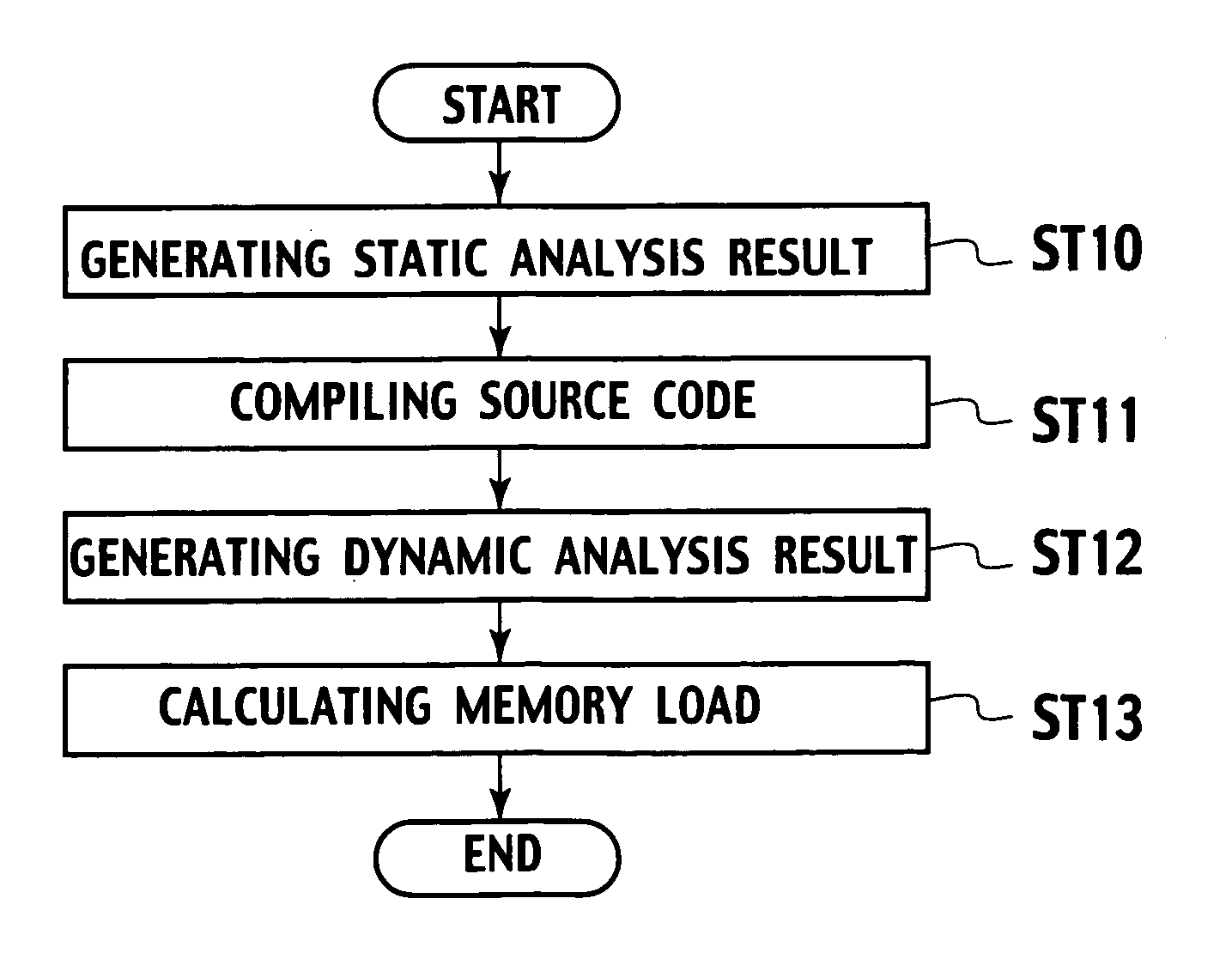
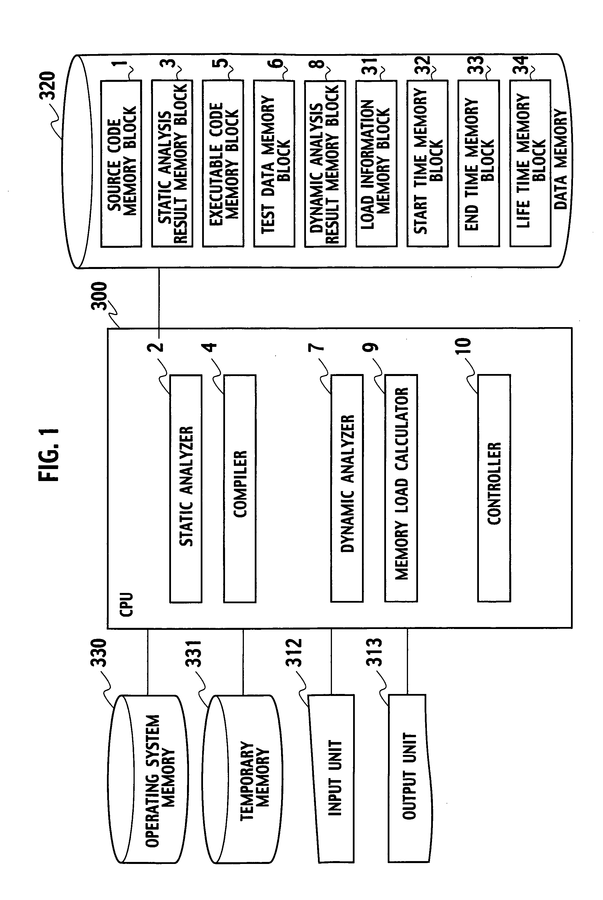
[0025] With reference to FIG. 1, a design evaluation system according to a first embodiment of the present invention includes a central processing unit (CPU) 300. The CPU 300 contains a static analyzer 2 configured to analyze a source code by sampling a plurality of functions and a plurality of variables related to the functions from the source code, a compiler 4 configured to compile the source code into an executable code, a dynamic analyzer 7 configured to analyze each life start time and each life end time of the variables in case where the executable code is executed, and a memory load calculator 9 configured to calculate each memory load of the variables by multiplying each life time of the variables by each size of the variables, the life time being difference between the life start time and the life end time.

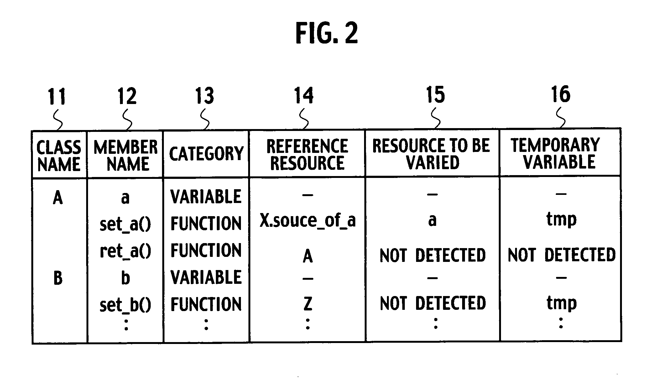
[0026] The static analyzer 2 is configured to statically analyze a source code written in an object-oriented language such as system C language. The program written in ...

second embodiment

[0081]FIGS. 9A to 9C show a process for memory load calculation which is performed by the design evaluation system for LSI according to a second embodiment of the present invention. FIG. 10 is a flowchart showing the design evaluation method for the system LSI according to the second embodiment of the present invention. The description is given with regard to the flow of operation for assisting in design according to the second embodiment with reference to FIG. 1, FIGS. 9A to 9C, and the flowchart of FIG. 10.

[0082] Here, the source code memory block 1 stores a class source 91 shown in FIG. 9A being equivalent to the module, and a class sum 92 shown in FIG. 9B. As shown in FIG. 9A, the class source 91 contains private member variables “a”, “b”, “c”, and “d” defined within the source code. The test data memory block 6 shown in FIG. 1 stores the test data which is used for the dynamic analyzer 7 to calculate the sum of the member variables “a”, “b”, “c”, and “d” using the class sum 92...

third embodiment

[0099]FIGS. 11A to 11C show a process for memory load calculation which is performed by the design evaluation system for the system LSI according to a third embodiment of the invention. FIG. 12 shows the design evaluation method for the system LSI according to the third embodiment of the invention. The description is given with regard to the flow of the design evaluation system according to the third embodiment with reference to FIG. 1, FIGS. 11A to 11C, and the flowchart of FIG. 12. As for the same structural components as the structural components of the second embodiment, the repeated description of the same structural components is omitted.

[0100] The dynamic analyzer 7 according to the third embodiment is different in configuration from the dynamic analyzer 7 of the second embodiment. At the completion of setting of each value of the member variables “a”, “b”, “c”, and “d” in each class contained in a class source 91a shown in FIG. 11A, the dynamic analyzer 7 informs a class su...


PUM


Abstract

A design evaluation system includes a static analyzer sampling functions and variables related to the functions from a source code, a compiler compiling the source code into an executable code, a dynamic analyzer sampling each life start time and each life end time of the variables in case where the executable code is executed, and a memory load calculator calculating each memory load of the variables by multiplying each life time of the variables by each size of the variables, the life time being difference between the life start time and the life end time.

Description

CROSS REFERENCE TO RELATED APPLICATIONS AND INCORPORATION BY REFERENCE [0001] This application is based upon and claims the benefit of priority from prior Japanese Patent Application P2004-090327 filed on Mar. 25, 2004; the entire contents of which are incorporated by reference herein. BACKGROUND OF THE INVENTION [0002] 1. Field of the Invention [0003] The invention relates to a design evaluation system and a design evaluation method for a system LSI, and more particularly to the apparatus and the method for assisting in design of the system LSI such as the system on chip using th-e electric design automation (EDA). [0004] 2. Description of the Related Art [0005] To manufacture a semiconductor integrated circuit having a few tens of thousands of gates, design departments have provided register transfer level (RTL) data to manufacturing departments. By providing the RTL data, it has been possible to manufacture the semiconductor integrated circuit, which works expectedly, until the s...

Claims


Application Information

Patent Timeline
IPC IPC(8): G06F17/50G06F9/44
CPCG06F11/3433G06F17/504G06F17/5022G06F11/3457G06F30/33G06F30/3323
Inventor IGARASHI, MASATO
Owner KK TOSHIBA
Why Eureka
Try Eureka