Disc cartridge

a technology of disc cartridges and cartridge cases, applied in the field of disc cartridges, can solve the problems of deformation of the cartridge case or the optical disc, and the reproducing apparatus and data is faultily recorded or reproduced

Inactive Publication Date: 2005-09-29
TDK CORPARATION
View PDF4 Cites 4 Cited by
  • Summary
  • Abstract
  • Description
  • Claims
  • Application Information

AI Technical Summary

Benefits of technology

[0008] A leading object of the present invention, which was made in view of the problems described above, is to provide a disc cartridge which can prevent that a cartridge main body and a disc-shaped recording medium are damaged and data is faultily recorded or reproduced due to the force applied to the cartridge main body while permitting the disc-shaped recording medium to be accessed.
[0010] In the disc cartridge, the reinforcing member formed independently of the upper shell is fixed to the inner surface of the upper shell so as to cross the disc access opening at the position where the reinforcing member does not overlap the disc-shaped recording medium in the thickness direction thereof. Accordingly, there can be provided the disc cartridge including the cartridge main body which is so rigid that it can be sufficiently prevented that the cartridge main body itself and the disc-shaped recording medium are damaged when external force is applied to the cartridge main body and that data is faultily recorded or reproduced due to the damage thereof. In this case, since the reinforcing member is fixed at the position where the reinforcing member does not overlap the disc-shaped recording medium in the thickness direction of the cartridge main body, the disc-shaped recording medium moving in the cartridge main body can be prevented from coming into contact with the reinforcing member and being damaged thereby. Therefore, occurrence of faulty recording or reproducing of data due to the damaged disc-shaped recording medium can be prevented. Further, there is employed the arrangement in which the reinforcing member formed independently of the upper shell is fixed to the inner surface of the upper shell. Accordingly, the upper shell can be formed of, for example, a transparent resin material (polycarbonate in this example) as well as the reinforcing member can be formed of a highly rigid member resistant to bending and twisting (metal, fiber-reinforced resin, and the like in this example) and fixed to the upper shell, thereby the rigidity of the cartridge main body can be sufficiently increased while securing the sufficient visually recognizing property to the disc-shaped recording medium through the upper shell and permitting employment of various designs.
[0011] In this case, the disc access opening may be formed from the one outside edge part of the lower shell to the other outside edge part thereof confronting the above outside edge part across the central portion thereof, and another reinforcing member formed independently of the upper shell may be fixed to the inner surface of the upper shell so as to cross a portion located at the other outside edge part of the lower shell in the disc access opening at the position where the reinforcing member does not overlap the disc-shaped recording medium accommodated in the cartridge main body in the thickness direction thereof. With the above arrangement, there can be provided the disc cartridge including the cartridge main body which is so rigid that it can be sufficiently prevented that the cartridge main body itself and the disc-shaped recording medium are damaged when external force is applied to the cartridge main body and that data is faultily recorded or reproduced due to the damage thereof while permitting data to be recorded to or reproduced from the disc-shaped recording medium using two optical heads at the same time.
[0013] The reinforcing member may be formed of fiber-reinforced resin (so-called filler resin). With the above arrangement, since the reinforcing member is lighter than the reinforcing member composed of a metal material, the weight of the disc cartridge can be reduced in its entirety while increasing the rigidity of the cartridge main body.
[0014] The reinforcing member may be fixed to the upper shell by caulking. With this arrangement, the reinforcing member can be fixed more easily in a shorter time than the arrangement for fixing the reinforcing member by, for example, screws and the like. Further, different from the arrangement for fixing the reinforcing member by an adhesive and the like, it can be prevented that a component, which is volatilized when the adhesive is dried, deposits on the surface and the like of the disc-shaped recording medium. Accordingly, the manufacturing cost of the disc cartridge can be sufficiently lowered while preventing that data is faultily recorded or reproduced due to the deposited component.
[0015] The reinforcing member may be formed in a flat shape and fixed to the upper shell such that the surface thereof is in parallel with the surface of a top plate of the upper shell. With this arrangement, there can be provided the disc cartridge including the cartridge main body having high rigidity in which the movement of the optical heads is not inhibited in the recording / reproducing apparatus.

Problems solved by technology

In this case, the cartridge case used in this type of the disc recording medium device (disc cartridge) must have a certain degree of rigidity to prevent that the cartridge case is deformed by external force applied thereto when the disc cartridge is carried in, for example, a bag and the like or by force applied thereto when the disc cartridge is loaded on a recording / reproducing apparatus and thus the cartridge case or the optical disc is damaged and that the cartridge case is deformed (deflected) in the recording / reproducing apparatus and data is faultily recorded or reproduced.
In contrast, it is difficult to increase the rigidity of the cartridge case by the intermediate shell and the shutter members because the intermediate shell and the shutter members are not fixed to any of the upper shell and the lower shell.
Accordingly, since the upper shell is only the member that can contribute to the rigidity of the cartridge case in a portion which overlaps the opening in the thickness direction thereof, the conventional disc recording medium device is much less resistant to force for bending or twisting the cartridge case.
As a result, a problem arises in that the cartridge case itself and the optical disc are damaged and that data is faultily recorded or reproduced.
When, however, this arrangement is employed, the optical disc in the cartridge case cannot be visually recognized through the upper shell because the glass-fiber-reinforced resin and the like is not transparent.
Therefore, the beauty of the cartridge case is spoiled as well as the design which can be employed to the cartridge case is limited to a very narrow range (design which prevents the visual recognition of the optical disc in the cartridge case) Further, it is also contemplated to employ an arrangement for increasing the rigidity of the cartridge case in its entirety by increasing the rigidity of the simple upper shell by sufficiently increasing the thickness thereof.
When, however, this arrangement is employed, since the thickness of the cartridge case is increased in its entirety by the increased thickness of the upper shell, it is difficult to satisfy the standard size of the disc recording medium device defined thereto.

Method used


Image

  • Disc cartridge
  • Disc cartridge
  • Disc cartridge

Examples


Embodiment Construction

[0034] Preferred embodiments of a disc cartridge according to the present invention will be explained below with reference to the attached drawings.

[0035] First, an arrangement of the disc cartridge 1 will be explained with reference to the drawings.

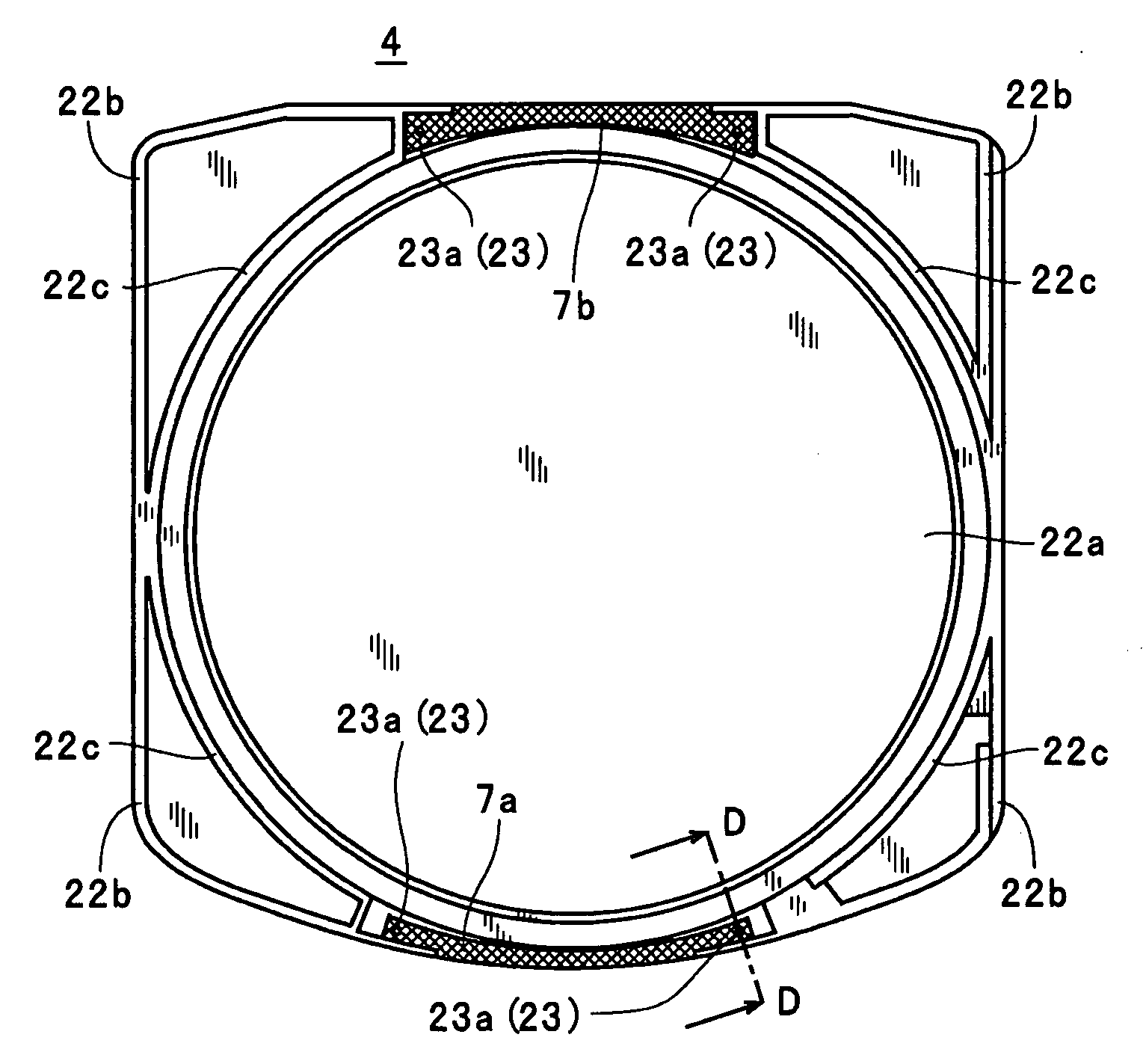
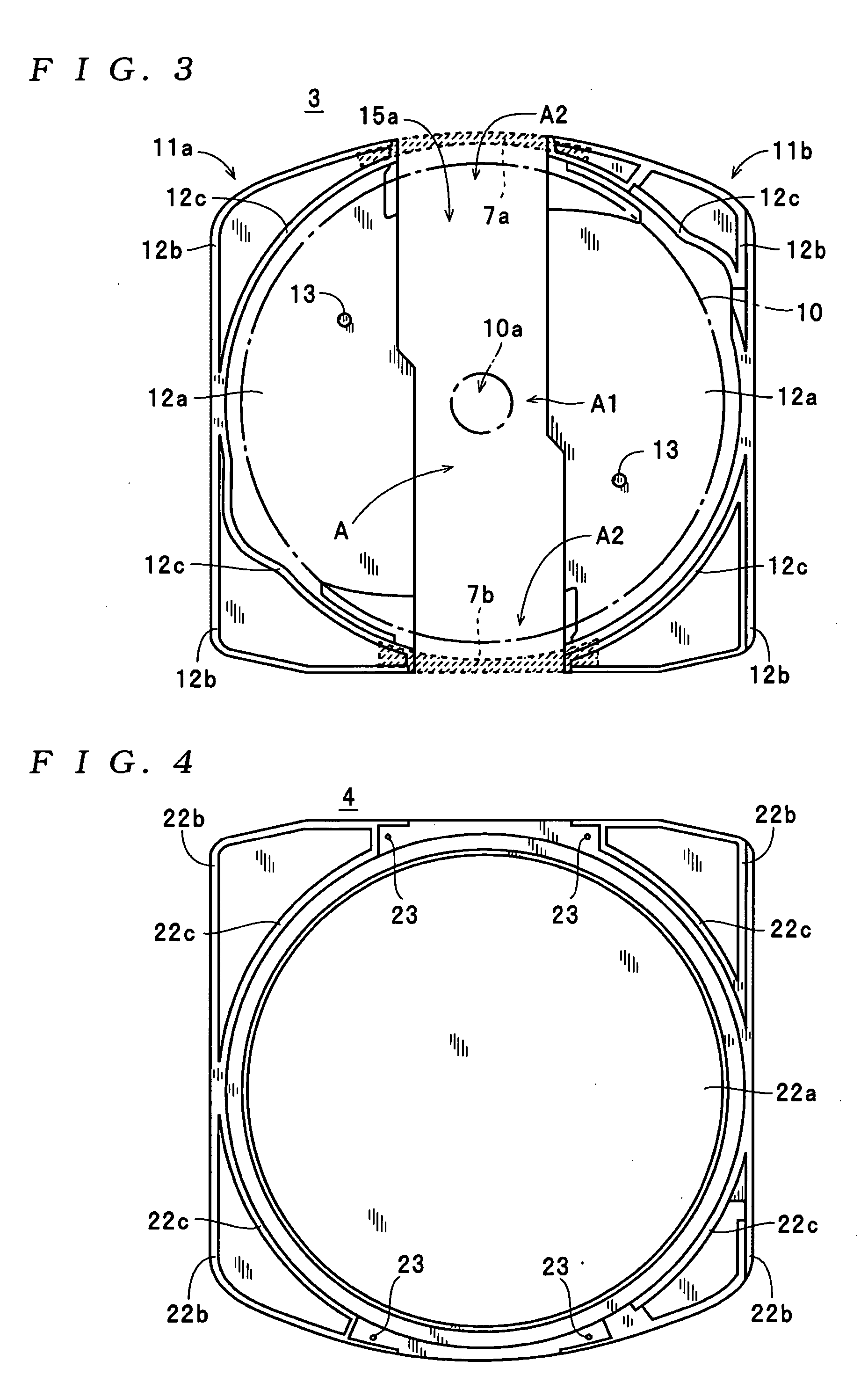
[0036] The disc cartridge 1 shown in FIGS. 1 and 2 is a cartridge type information recording medium which can record and reproduce various types of data, includes a cartridge main body 2, a disc tray 5, shutter members 6, and the like, and can accommodate an optical disc 10 therein. In FIG. 2, the disc cartridge 1 is shown thick in the thickness direction thereof with exaggeration so that the present invention can be easily understood. In this case, the optical disc 10 is, for example, a single-sided rewritable disc-shaped recording medium. As shown in FIG. 2, the optical disc 10 includes a central hole 10a having a diameter of about 15 mm and formed at the center thereof so that it is sandwitched to a recording / reproducing apparatus t...


PUM

PropertyMeasurementUnit
diameteraaaaaaaaaa
thicknessaaaaaaaaaa
thicknessaaaaaaaaaa

Abstract

A disc cartridge includes a disc-shaped recording medium accommodated in a cartridge main body having a lower shell and an upper shell overlapping each other, a disc access opening formed from one outside edge part of the lower shell to a central portion thereof to expose a belt-shaped region of the disc-shaped recording medium accommodated in the cartridge main body from the central region thereof to at least the outside edge part region thereof, and a reinforcing member formed independently of the upper shell and fixed to the inner surface of the upper shell so as to cross a portion located at the outside edge part of the lower shell in the disc access opening at the position where the reinforcing member does not overlap the disc-shaped recording medium accommodated in the cartridge main body in the thickness direction thereof.

Description

BACKGROUND OF THE INVENTION [0001] 1. Field of the Invention [0002] The present invention relates to a disc cartridge arranged such that a disc-shaped recording medium is accommodated in a cartridge main body having a lower shell and an upper shell. [0003] 2. Description of the Related Art [0004] Japanese Laid-Open Patent Publication No. 2003-115181 discloses a disc recording medium device which accommodates an optical disc in a cartridge case (disc accommodation chamber) as this type of the disc cartridge. As shown in FIG. 1 of the publication, the disc recording medium device includes the cartridge case having an upper shell, an intermediate shell, and a lower shell, the optical disc accommodated in the disc accommodation chamber, and shutter members interposed between the intermediate shell and the lower shell. In this case, the intermediate shell acts as a disc tray on which the optical disc is placed and is accommodated in the disc accommodation chamber together with the optica...

Claims


Application Information

Patent Timeline
Patent Type & Authority Applications(United States)
IPC IPC(8): G11B23/03
CPCG11B23/0308
Inventor HASHIZUME, KENJISASAKI, MORIMASA
Owner TDK CORPARATION
Why Eureka
Try Eureka