Drying device and method of operation therefor

Inactive Publication Date: 2005-10-06
PANASONIC CORP
View PDF6 Cites 55 Cited by
  • Summary
  • Abstract
  • Description
  • Claims
  • Application Information

AI Technical Summary

Benefits of technology

[0010] It is another object of the invention to provide a drying apparatu

Problems solved by technology

Due to the current carrying capacity of a domestic convenience receptacle, its amount of heat is limited, and this causes a bottleneck in reduction of time required for drying clothing.
Further, heat used for drying clothing is not reused and is only discharged out, and this is waste of energy.
If heat which is greater than the optimal amount of heat to be d

Method used


Image

  • Drying device and method of operation therefor
  • Drying device and method of operation therefor
  • Drying device and method of operation therefor

Examples


first embodiment

(First Embodiment)

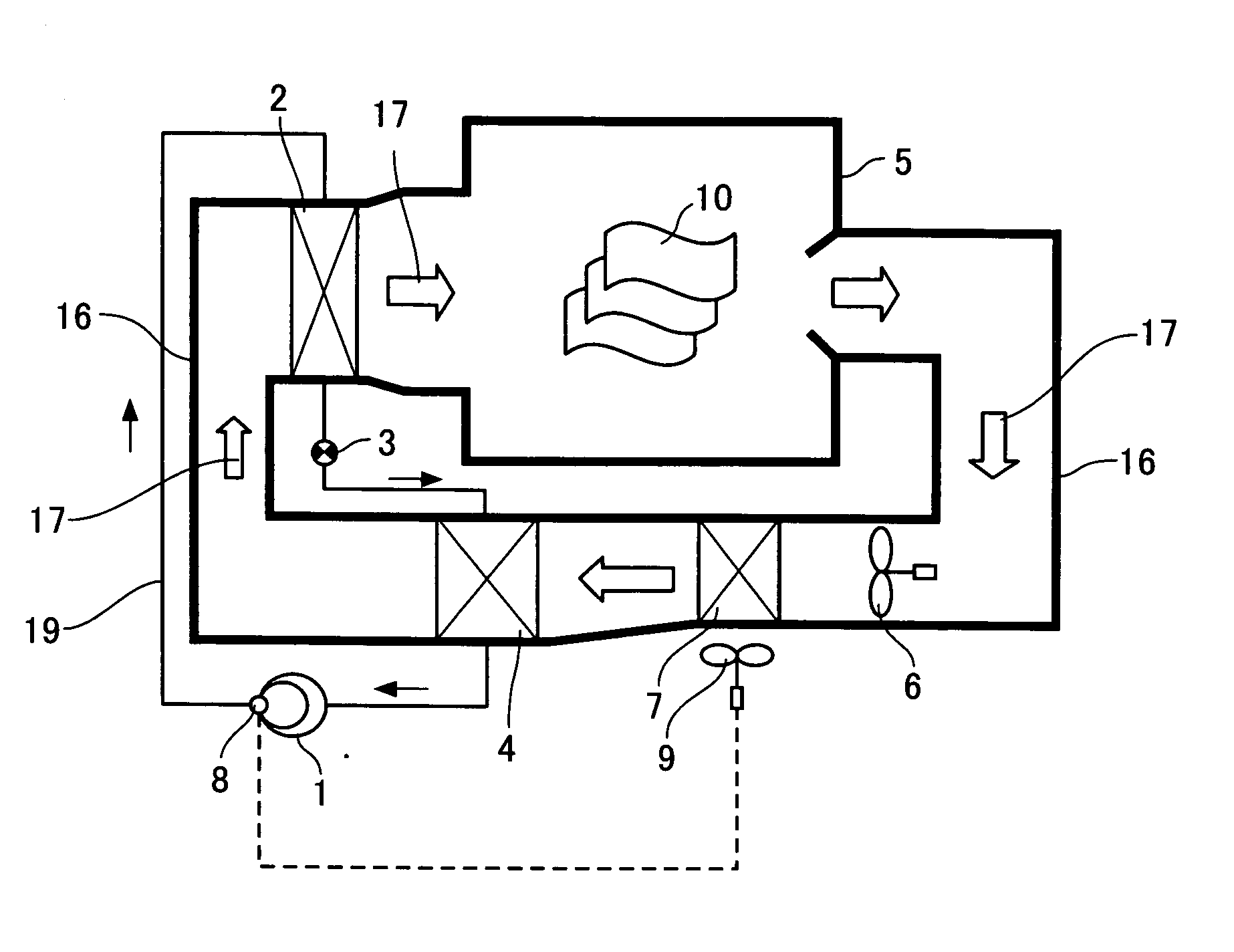
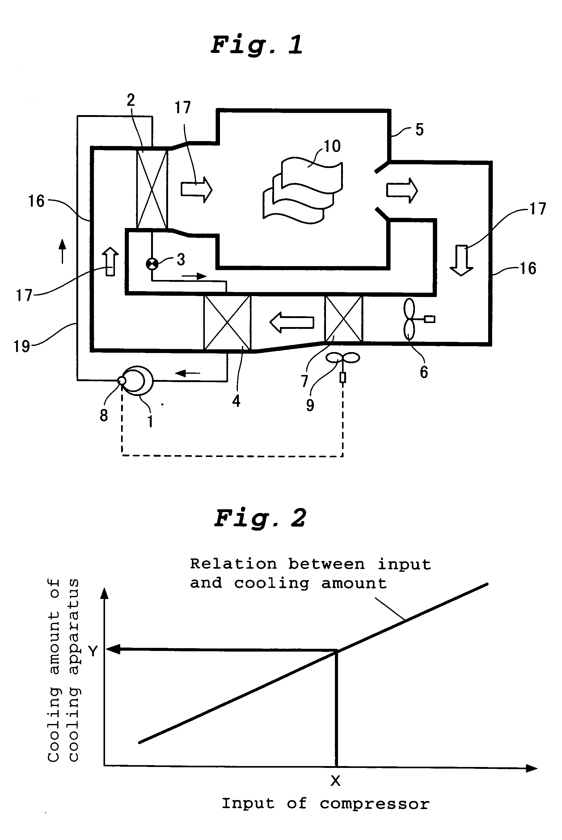
[0056]FIG. 1 is a block diagram of a drying apparatus of a first embodiment of the present invention. The drying apparatus of this embodiment uses a refrigerant of flon, carbon dioxide or the like as working fluid, and has a heat pump apparatus. In the heat pump apparatus, a compressor 1, a radiator 2, a throttle apparatus 3 and an evaporator 4 are connected to one another through pipes 19. The drying apparatus includes a dry chamber 5 which dries a subject to be dried 10 such as clothing by drying air 17 heated by the radiator 2, a blower 6 for sending the drying air 17, and a cooling apparatus 7 for cooling the drying air 17. The drying air 17 circulates through the radiator 2, the dry chamber 5, the cooling apparatus 7 and the evaporator 4 via a duct 16. The drying apparatus includes compressor input detecting means 8 for detecting input of the compressor 1, and cooling quantity control means 9 for controlling the cooling quantity of the cooling apparatus 7 base...

second embodiment

(Second Embodiment)

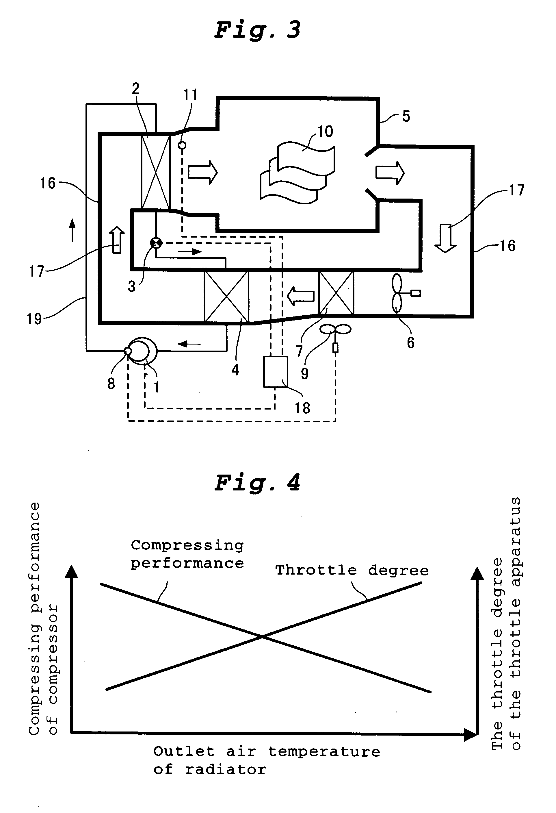
[0063]FIG. 3 is a block diagram showing a drying apparatus of a second embodiment of the invention. Only difference of the structure of the drying apparatus of the second embodiment from those of the first embodiment will be explained. The same can be applied to third and subsequent embodiments also.

[0064] The drying apparatus of the second embodiment includes, in addition to the structure of the first embodiment, outlet air temperature detecting means 11 for detecting the outlet air temperature of the radiator 2, and refrigeration cycle control means 18 for controlling compressing performance of the compressor 1 and the throttle degree of the throttle apparatus 3 based on the outlet air temperature.

[0065] The outlet air temperature detecting means 11 comprises a temperature sensor for example, and detects the temperature of the drying air 17 at the outlet of the radiator 2. The refrigeration cycle control means 18 comprises means for adjusting operating frequen...

third embodiment

(Third Embodiment)

[0071]FIG. 6 is a block diagram showing a drying apparatus of a third embodiment of the invention, and FIG. 7 is a control flowchart of the drying apparatus of the third embodiment.

[0072] The drying apparatus of the third embodiment includes discharge pressure detecting means 12 for detecting discharge pressure of the compressor 1, and refrigeration cycle control means 18 for controlling the compressing performance of the compressor 1 and the throttle degree of the throttle apparatus 3 based on the detected discharge pressure.

[0073] The operation of the drying apparatus will be explained below.

[0074] As shown in FIG. 7, in step 41, the refrigeration cycle control means 18 compares discharge pressure Pm detected by the discharge pressure detecting means 12 and target upper limit set pressure Px (e.g., 12 MPa) with each other. If Pm is greater than Px, it is determined that the discharge pressure exceeds a reliability reference value of the compressor, the procedu...


PUM


Abstract

A drying apparatus comprising a heat pump apparatus in which a refrigerant circulates through a compressor, a radiator, a throttle apparatus and an evaporator in this order, in which air heated by the radiator is introduced into a dry chamber, the air coming out from the dry chamber is cooled by a cooling apparatus, the air cooled by the cooling apparatus is dehumidified by the evaporator, and the air dehumidified by the evaporator is again heated by the radiator, wherein the drying apparatus further comprises compressor input detecting means for detecting input of the compressor, and cooling quantity control means for controlling a cooling quantity of the cooling apparatus using a value detected by the compressor input detecting means.

Description

TECHNICAL FILED [0001] The present invention relates to a drying apparatus having a heat pump apparatus in which a refrigerant circulates through a compressor, a radiator, a throttle apparatus and an evaporator in this order, wherein air heated by the radiator is introduced into a dry chamber, the air coming out from the dry chamber is cooled by a cooling apparatus, and the air cooled by the cooling apparatus is dehumidified by the evaporator, and the air dehumidified by the evaporator is again heated by the radiator. The invention also relates to an operating method of the drying apparatus. BACKGROUND OF THE INVENTION [0002] An electric clothing dryer used in ordinary households uses an electric heater as a heat source which is necessary for drying. Due to the current carrying capacity of a domestic convenience receptacle, its amount of heat is limited, and this causes a bottleneck in reduction of time required for drying clothing. Further, heat used for drying clothing is not reus...

Claims


Application Information

Patent Timeline
IPC IPC(8): D06F58/20F24F3/153F25B9/00F26B21/08
CPCD06F58/206D06F2058/287F26B21/086F25B9/008F25B2309/061F24F3/153D06F2103/50D06F2105/26D06F2103/36D06F2105/24D06F58/48D06F58/50D06F58/46D06F2103/32D06F2103/34Y02B40/00
Inventor YAKUMARU, YUUICHITAMURA, TOMOICHIRONISHIWAKI, FUMITOSHI
Owner PANASONIC CORP
Why Eureka
Try Eureka