Energy balanced weld controller

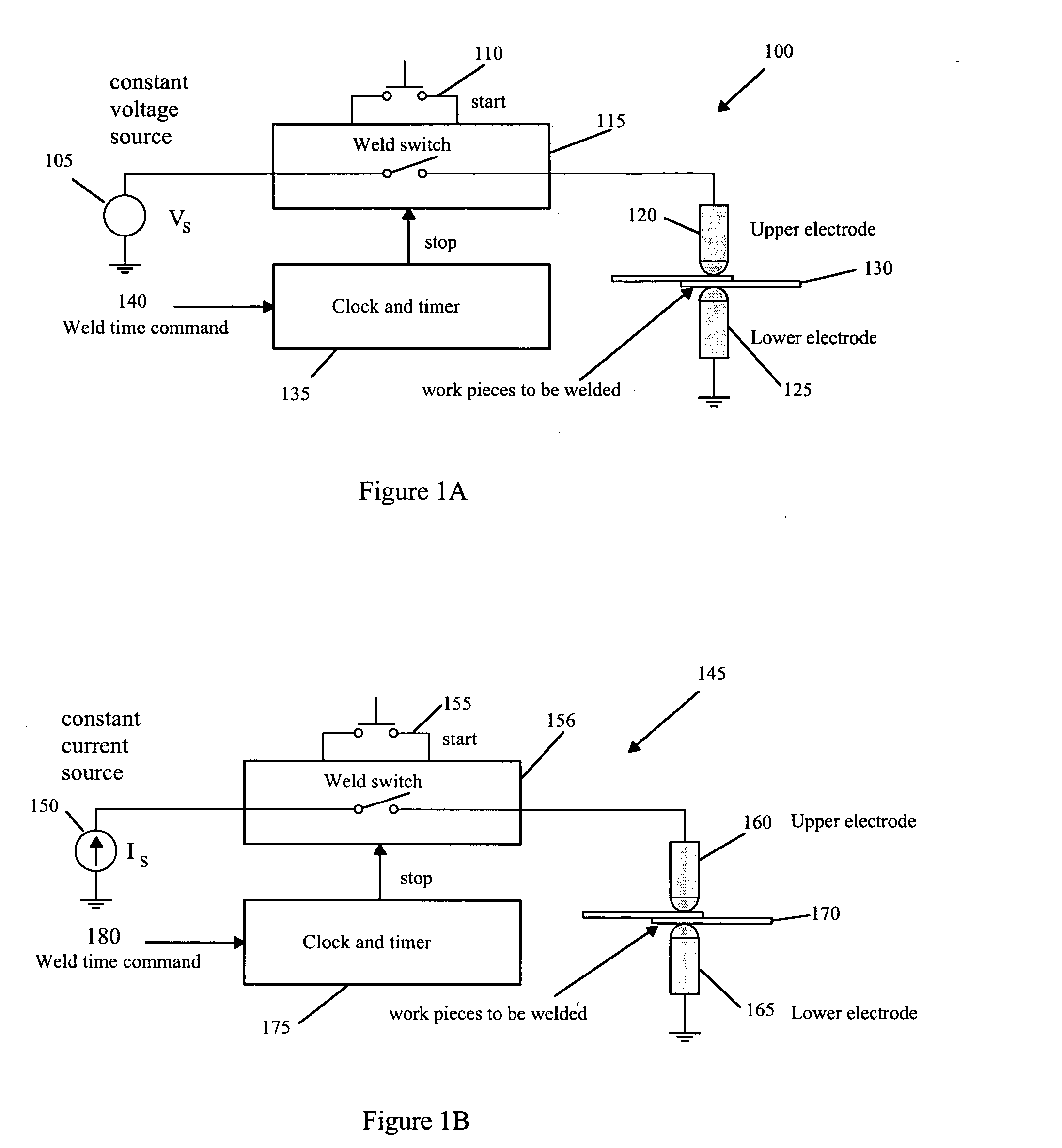
a technology of energy balance and weld controller, which is applied in the direction of welding monitoring devices, manufacturing tools, welding apparatus, etc., can solve the problems of large amount of energy being delivered to the weld, constant voltage controller b>100/b> cannot compensate for the resistance change of the stack of work pieces, and the constant voltage controller b>100/b> cannot deliver enough energy to form an adequate sized nugg

Inactive Publication Date: 2005-10-06
SHIH KELVIN
View PDF13 Cites 14 Cited by
  • Summary
  • Abstract
  • Description
  • Claims
  • Application Information

AI Technical Summary

Benefits of technology

[0018] An energy balanced weld controller includes a mid frequency direct current power supply that supplies power to a welder and a weld switch that turns the current to weld caps on or off. A Rogowski coil and an integrator measure the secondary weld current provided to the weld, and a pair of tip wires connected to the weld caps detect the tip voltage. A low pass filter filters out all induced noise from the tip voltage.

Problems solved by technology

However, the constant voltage controller 100 cannot compensate for changes in the resistance of the stack of work pieces 130 caused by anomaly in the stack.
If the resistance of the stack is too high, the constant voltage controller 100 will not deliver not enough energy to form an adequately sized nugget.
If the resistance of the stack is too low, too much energy is delivered to the weld, and expulsion may occur.
However, the constant current controller 145 cannot compensate for changes in the resistance of the stack of workpieces 170 caused by anomaly in the stack.
However, too much energy could cause expulsion and create a bad weld.
If the resistance is too low, not enough energy is supplied to the weld, creating an under-sized nugget.
Expulsion is the eruption of molten metal, which can deteriorate the quality of the nugget.
Expulsion can be caused by excessive energy delivered to the nugget or can be caused by a large current density, even if the right amount of energy is delivered to the weld.
If the weld lobe is large enough, a satisfactory weld is formed, even if the chosen schedule is inaccurate.
Unfortunately, most of the schedules are too aggressive, and expulsions may result.
A drawback to both constant voltage and constant current weld controllers is that they are open loop systems and cannot accurately control the weld.
Therefore, a mediocre or inferior weld quality can result.

Method used


Image

  • Energy balanced weld controller
  • Energy balanced weld controller
  • Energy balanced weld controller

Examples


Embodiment Construction

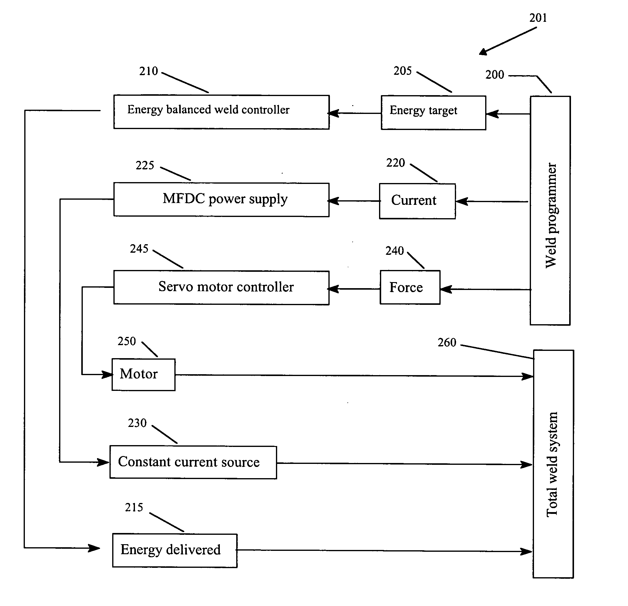
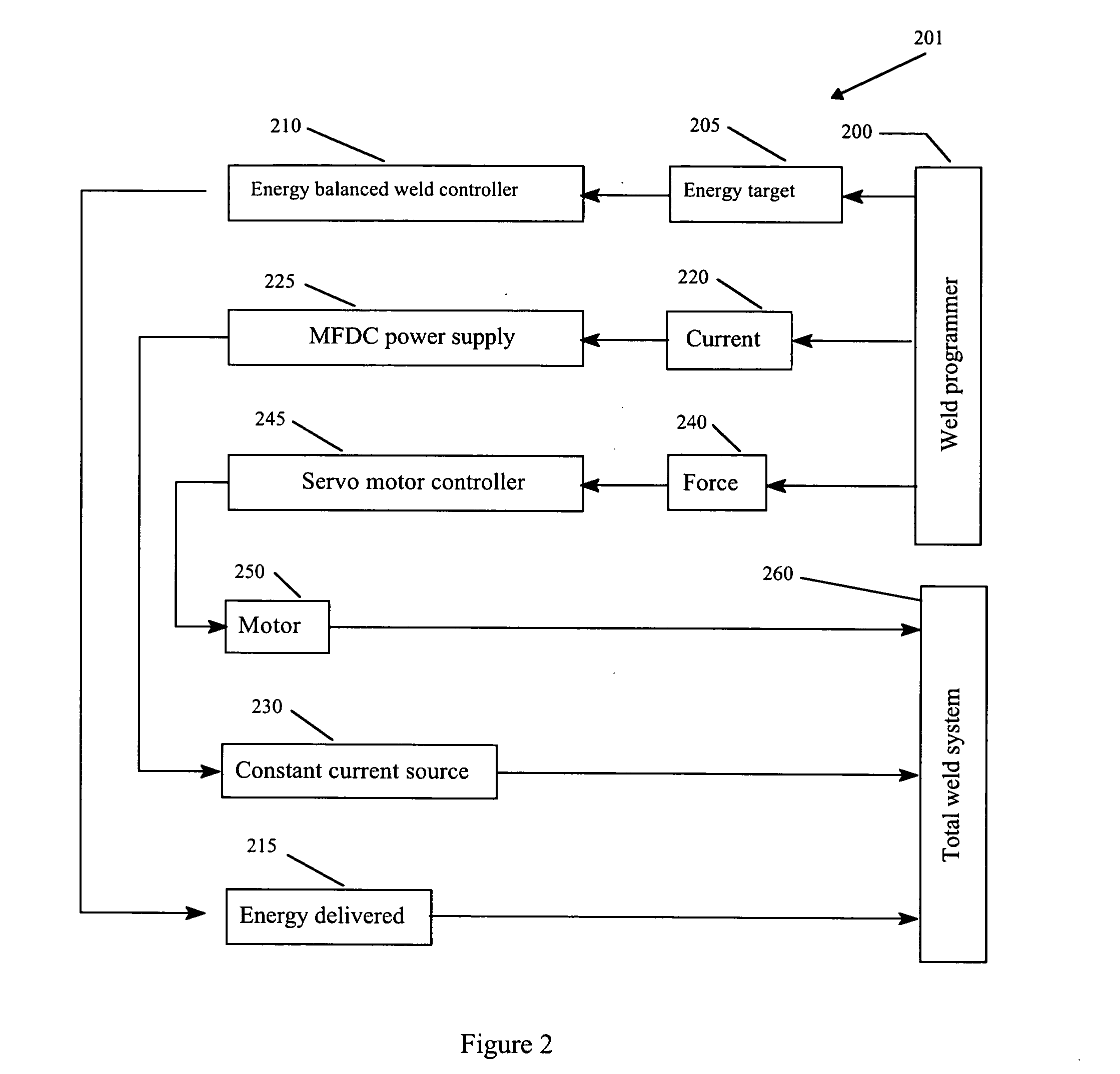
[0035]FIG. 2 illustrates a system diagram of an energy balanced weld system 201 of the present invention. A weld programmer 200 supplies a programmed energy target command 205, a programmed current command 220 and a programmed force command 240. The programmed energy target command 205 includes four-digit binary coded digital (BCD) or DC voltage (in all analog implementation) energy target information that is supplied to an energy balanced weld controller 210. The energy balanced weld controller 210 delivers an exact amount of the energy 215 to a total weld system 260. The programmed current command 220 is provided to a mid frequency direct current power supply 225 to control the Isolated Gate Bipolar Transistors and to provide a constant weld current 230 to the total weld system 260. The current control signal can either be a voltage or a digital coded signal. The programmed force command 240 is provided to a servomotor controller 245 which controls the direction, the speed, and th...


PUM

PropertyMeasurementUnit
frequencyaaaaaaaaaa
frequencyaaaaaaaaaa
thicknessaaaaaaaaaa

Abstract

An energy balanced weld controller includes a mid frequency direct current power supply and a weld switch that turns the current to weld caps on or off. The weld caps are used to produce a weld on workpieces. The tip voltage and the weld current are multiplied to generate a voltage which is converted to a frequency. The output represents the amount of energy provided to the weld and is provided to a frequency counter that counts the amount of energy delivered to the weld. A magnitude comparator compares the energy delivered to the weld to a target energy. When the energy delivered to the weld equals the target energy, the magnitude comparator sends a high signal to the weld switch to terminate the weld.

Description

REFERENCE TO RELATED APPLICATION [0001] This application claims priority to U.S. Provisional Application No. 60 / 559,899 filed on Apr. 6, 2004.BACKGROUND OF THE INVENTION [0002] The present invention relates generally to a closed loop energy balanced weld controller for a resistance welder that measures the energy provided to a weld and stops welding when an amount of energy provided to the weld equals a preset target energy. [0003] Most controllers for resistance welders using alternating current (AC) or mid frequency direct current (MFDC) are either constant voltage (CV) or constant current (CI). Both constant voltage and constant current controllers operate in an open loop configuration. [0004]FIG. 1A illustrates a typical constant voltage controller 100 for a resistance welder. The constant voltage controller 100 includes a low voltage and high current voltage source 105 (Vs) that maintains a tip voltage at a constant level. In alternating current welding, Silicon Controlled Rect...

Claims


Application Information

Patent Timeline
Patent Type & Authority Applications(United States)
IPC IPC(8): B23K11/24B23K11/25
CPCB23K11/258B23K11/257
Inventor SHIH, KELVIN
Owner SHIH KELVIN
Why Eureka
Try Eureka