Fuel pump, fuel supply equipment using fuel pump and method for manufacturing fuel pump

a fuel pump and fuel supply technology, applied in the direction of piston pumps, positive displacement liquid engines, magnetism circuit shapes/forms/construction, etc., can solve the problems of short motor life, reduced motor efficiency, and reduced motor efficiency, so as to reduce sliding resistance and fluid resistance, the effect of increasing the pressure of the fuel and increasing the curren

Inactive Publication Date: 2005-10-06
DENSO CORP
View PDF6 Cites 20 Cited by
  • Summary
  • Abstract
  • Description
  • Claims
  • Application Information

AI Technical Summary

Benefits of technology

[0023] The inventions described in claims are operated such that some magnetic poles formed in a circumferential direction of a stator core are changed over under controlling of an electrical energization for the coils wound around the stator core, the rotating members at the pump is rotated together with the rotor through the changing-over of the magnetic poles and a pressure of the fuel is increased. That is, the fuel pump using the brushless motor is installed in the fuel tank of the motorcycle. Both sliding resistance and fluid resistance can be reduced as compared with those of the commutator controlled motor because no commutator is used in the brushless motor. With such an arrangement as above, a motor size can be reduced and its low current can be attained under the same output because the aforesaid motor efficiency is improved with the result that the fuel pump efficiency is improved. Accordingly, it is possible to mount the fuel pump within the fuel tank of the motorcycle having a smaller size as compared with that of a four-wheeled vehicle.
[0024] In addition, no electrical corrosion or corrosion occurs at the sliding portion between the commutator and the brush as found in the commutator controlled motor even if the deteriorated fuel or low quality fuel is used because no commutator is used in the brushless motor. Further, a life of the fuel pump is extended because no sliding wear is produced between the commutator and the brush.

Problems solved by technology

However, the motor controlled by the commutator has some disadvantages that a motor efficiency is decreased with the result that an efficiency of the motor is decreased because a sliding resistance between the commutator and a brush and a fluid resistance received at the grooves formed for dividing the commutator into each of the segments are generated.
In addition, the motor controlled by the commutator shows a problem that a motor lifetime becomes short due to a wearing at the sliding locations between the commutator and the brush.
As described above, when a height of the fuel pump installed in the fuel tank is increased, there occurs a problem that a structure for installing the fuel pump in the fuel tank becomes complex.
When it is tried to utilize the fuel pump having a commutator controlled motor of a four-wheeled vehicle as a driving source for a motorcycle where a battery capacity that can be mounted on the motorcycle is low due to a narrow installing space, an assurance of electrical power supplied to the fuel pump sometimes becomes difficult because an efficiency of the fuel pump is low.
In addition, when the fuel tank is small in size for the motorcycle, it is difficult to mount the fuel pump in the fuel tank.
Additionally, deteriorated fuel or low quality fuel containing alcohol, for example, may be used in a motorcycle and when the fuel pump having a commutator controlled motor is mounted on the motorcycle utilizing such a deteriorated fuel or low quality fuel as above, electric corrosion or corrosion may occur at the sliding contact portion between the commutator and the brush and an inferior electrical conduction state may occur.
There occurs a problem in the brushmotor that a motor efficiency is reduced with the result that a fuel pump efficiency is reduced by a sliding resistance between the commutator and the brush as well as a fluid resistance received at the grooves arranged for dividing the commutator into each of the segments.
In addition, the brushmotor has a problem that the motor life becomes short due to a wearing of the sliding portion between the commutator and the brush.
Additionally, when deteriorated fuel or low quality fuel is used as fuel, application of the brushmotor to the fuel pump causes the sliding portion between the commutator and the brush to generate an electrical corrosion or poor electrical contact and there occurs a possibility that an electrical non-conductive state is produced.
In addition, when the coil of the rotor in the aforesaid brushmotor is formed in a distributed winding type where the coil is wound over a plurality of teeth, the windings at the coil ends are crossed to each other and it becomes difficult to increase a rate of occupancy of the winding per magnetic pole.
However, it is hard to seal between the bearing slidingly contacted with the rotary shaft and the pump chamber, and the Patent Document 2 does not disclose a structure for sealing between the pump chamber and the bearing.
In addition, even if the pump chamber and the bearing can be sealed to each other, there remains a problem that a sliding resistance is increased and the sliding friction is increased because the sliding part between the rotary shaft and the bearing is not lubricated with fuel.

Method used


Image

  • Fuel pump, fuel supply equipment using fuel pump and method for manufacturing fuel pump
  • Fuel pump, fuel supply equipment using fuel pump and method for manufacturing fuel pump
  • Fuel pump, fuel supply equipment using fuel pump and method for manufacturing fuel pump

Examples


first preferred embodiment

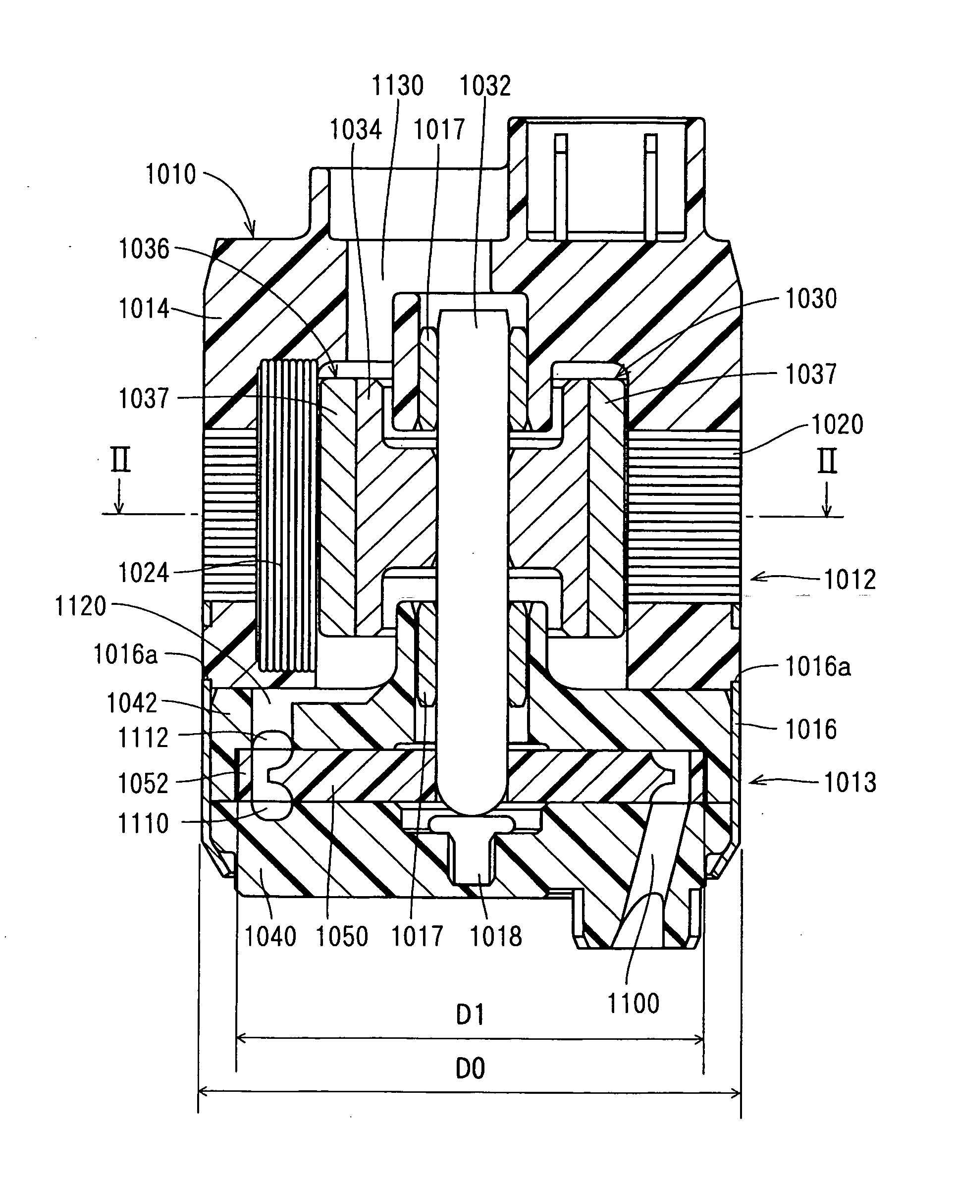
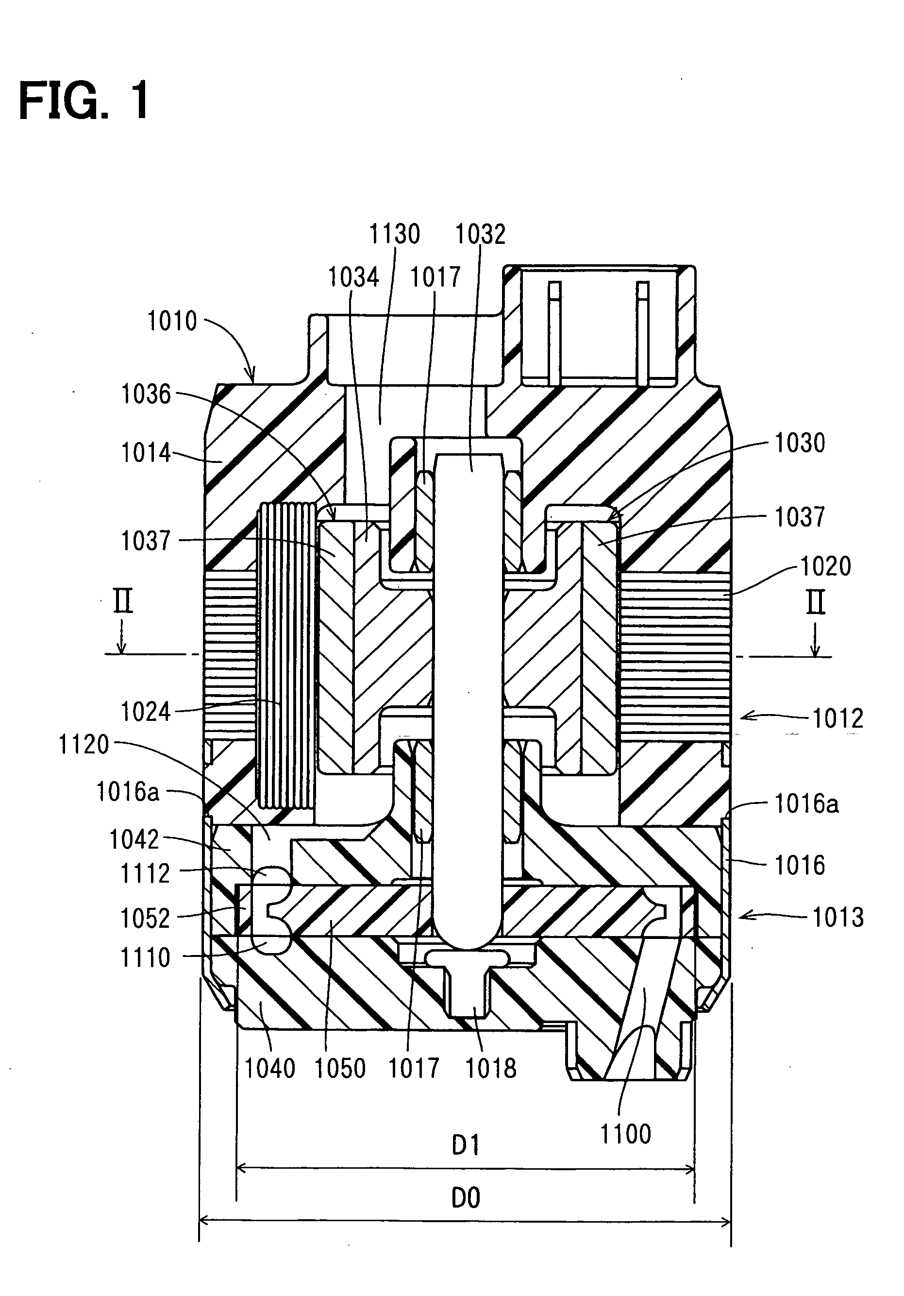
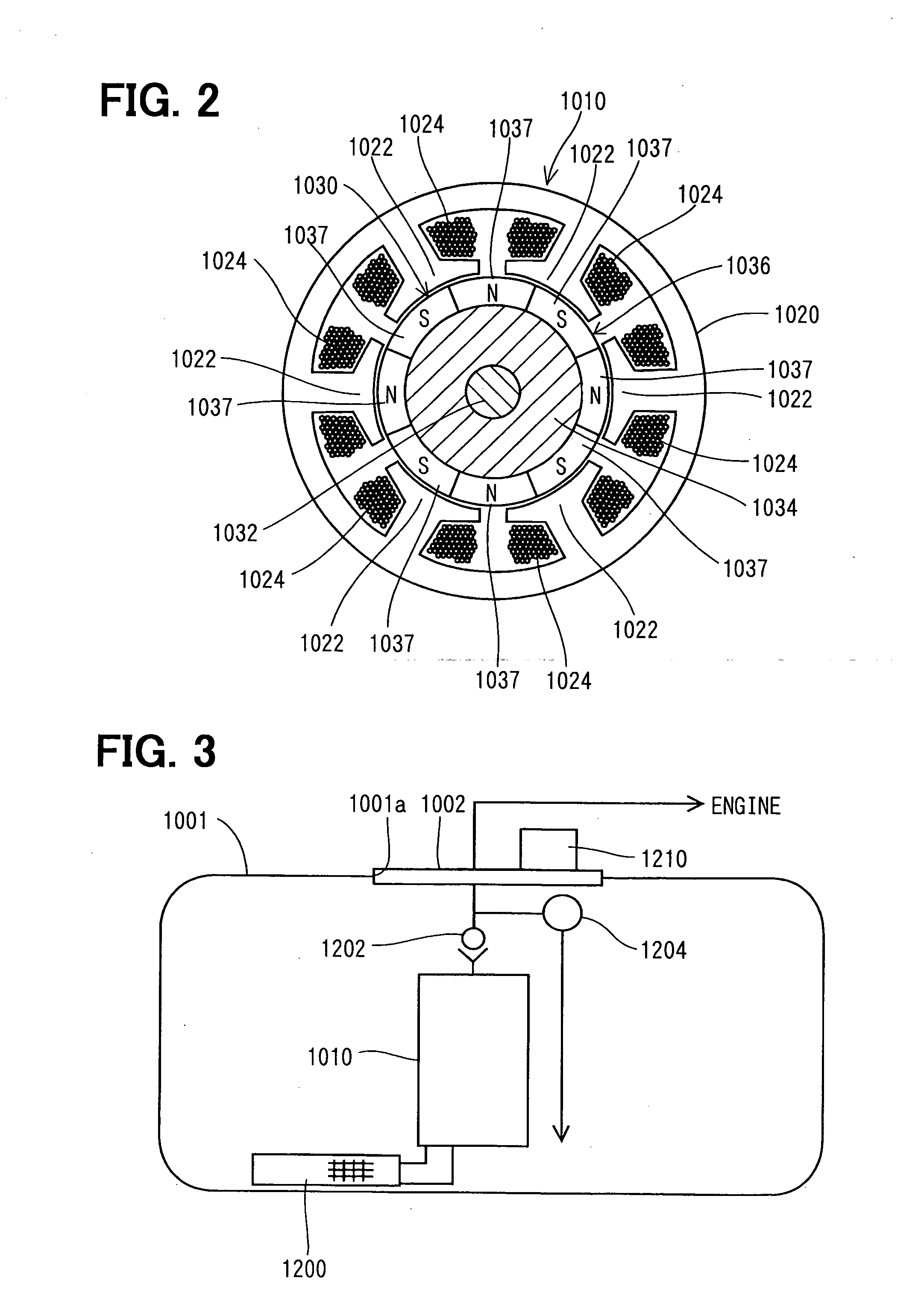
[0056] In FIG. 3 fuel supply equipment using the fuel pump in accordance with the first preferred embodiment of the present invention is illustrated. Afuel pump 1010 in the fuel supply equipment is an in-tank type Wesco pump mounted in a fuel tank 1001 of a motorcycle. A fuel discharging amount required in the fuel pump 1010 is 5 L / h or more to 30 L / h or less. The fuel pump 1010 discharges the fuel in the fuel in the fuel tank 1001 sucked through a suction filter 1200 while its pressure is being increased. The fuel discharged by the fuel pump 1010 passes through a check valve 1202 and a fuel pressure is adjusted by a pressure regulator 1204 and the fuel is fed to the engine acting as a fuel consuming device.

[0057] A control device 1210 for use in controlling the driving current fed to the fuel pump 1010 is fixed outside the fuel tank 1001 of the lid member 1002 for closing an opening of the fuel tank 1001. A capacity of the battery of a motorcycle not shown for feeding the driving ...

second preferred embodiment

[0069] In FIG. 7 is illustrated the second preferred embodiment. This preferred embodiment is substantially the same as the constitution of the first preferred embodiment except the fact that the pump 1060 is different from the pump 1013 in the first preferred embodiment. Substantially the same composing portions as those of the first preferred embodiment are denoted by the same reference symbols.

[0070] In the second preferred embodiment, the pump 1060 constitutes a trochoid pump. An outer rotor 1064 is stored at the inner circumferential side of the housing 1062, and an inner rotor 1066 is stored at the inner circumference of the outer rotor 1064. Inner teeth 1065 formed at the inner circumference of the outer rotor 1064 are engaged with outer teeth 1067 formed at the outer circumference of the inner rotor 1066. The center of the outer rotor 1065 is eccentric with respect to the center of the inner rotor 1066, and the number of inner teeth 1065 is larger by 1 than that of the oute...

third preferred embodiment

[0071] In FIG. 8 is shown the third preferred embodiment of the present invention. Substantially the same composing elements as those of the first preferred embodiment are denoted by the same reference symbols.

[0072] In the third preferred embodiment, a control device 1220 comprises a three-phase circuit 1230, a current detector 1240 and a PWM (Pulse Width Modulation) control part 1250. The three-phase circuit 1230 in the third preferred embodiment is substantially the same circuit as that of the control device 1210 shown in FIG. 5. The three-phase circuit 1230, the current detector 1240 and the PWM control part 1250 are constituted by one tip IC element as one circuit module.

[0073] The current detector 1240 compares a total amount of currents flowing in six coils 1024 of the fuel pump 1010 with a predetermined value and transmits the result to the PWM control part 1250.

[0074] At the PWM control part 1250 acting as a limiting circuit a corresponding table is made for the PWM valu...


PUM


Abstract

A fuel pump mounted in the fuel tank for the motor cycle comprises a motor and a pump driven by the motor for increasing a pressure of the sucked fuel. The motor is a brushless motor and has a stator core, coils and a rotor. An electrical energization for the coils wound around the stator core is controlled in response to a rotating position of the rotor, thereby the rotor is rotated. The rotor has a shaft, a rotating core and a permanent magnet, and the rotor is rotatably mounted at the inner circumference of the stator core. The permanent magnet is mounted at the outer circumference of the rotating core and magnetically energized so as to form magnetic poles different alternatively in a rotating direction at the outer circumferential surface facing the stator core.

Description

CROSS-REFERENCE TO RELATED APPLICATION [0001] This application is based on Japanese Patent Applications No. 2004-110164 filed on Apr. 2, 2004, No. 2004-266739 filed on Sep. 14, 2004, No. 2004-327367 filed on Nov. 11, 2004, and No. 2004-355575 filed on Dec. 8, 2004, the disclosure of which is incorporated herein by reference. FIELD OF THE INVENTION [0002] This invention relates to an in-tank type fuel pump for a motorcycle, fuel supply equipment using the fuel pump and a method for manufacturing the fuel pump. BACKGROUND OF THE INVENTION [0003] In general, it has been well known in the art to provide a motor in which a current fed to a rotor having a coil wound around it is controlled by a commutator and the rotor is rotated. Then, as a driving source for a fuel pump for absorbing the fuel in the fuel tank and feeding the fuel to an engine acting as a fuel consumption device, there has been used the motor controlled by the commutator as described above (refer to Patent Document 1, fo...

Claims


Application Information

Patent Timeline
Patent Type & Authority Applications(United States)
IPC IPC(8): F02M37/00F02M37/10F04B17/00F04B35/04F04D5/00H02K1/14H02K15/095H02K29/00
CPCF02M37/048F04D5/002F02M37/10H02K15/095H02K1/148
Inventor NAGATA, KIYOSHIMOROTO, KIYONORIKUROIWA, KAZUNARIOTAKE, MASAYA
Owner DENSO CORP
Why Eureka
Try Eureka