EXAMPLE
[0053] Hereinafter, the present invention will be described in detail with reference to the case in which the valve of the present invention is applied to a small fuel cell. However, the present invention is not limited to the small fuel cell.
[0054] As an effective example of the valve according to the present invention, the case will be described in which the valve of the present invention is used for a small fuel cell which is mounted in an electrical device such as a portable device. FIG. 11 is a schematic view showing the case in which the valve of the present invention is applied to a fuel cell. A fuel cell 17 is composed of a power generation portion 19, a hydrogen storage container 20 having a hydrogen absorbing alloy, a valve 18, and an exhaust valve 21. In this fuel cell, the valve 18 is provided at a connection portion 25 between the power generation portion 19 and the hydrogen storage container 20, and the exhaust valve 21 is provided for the power generation portion 19.
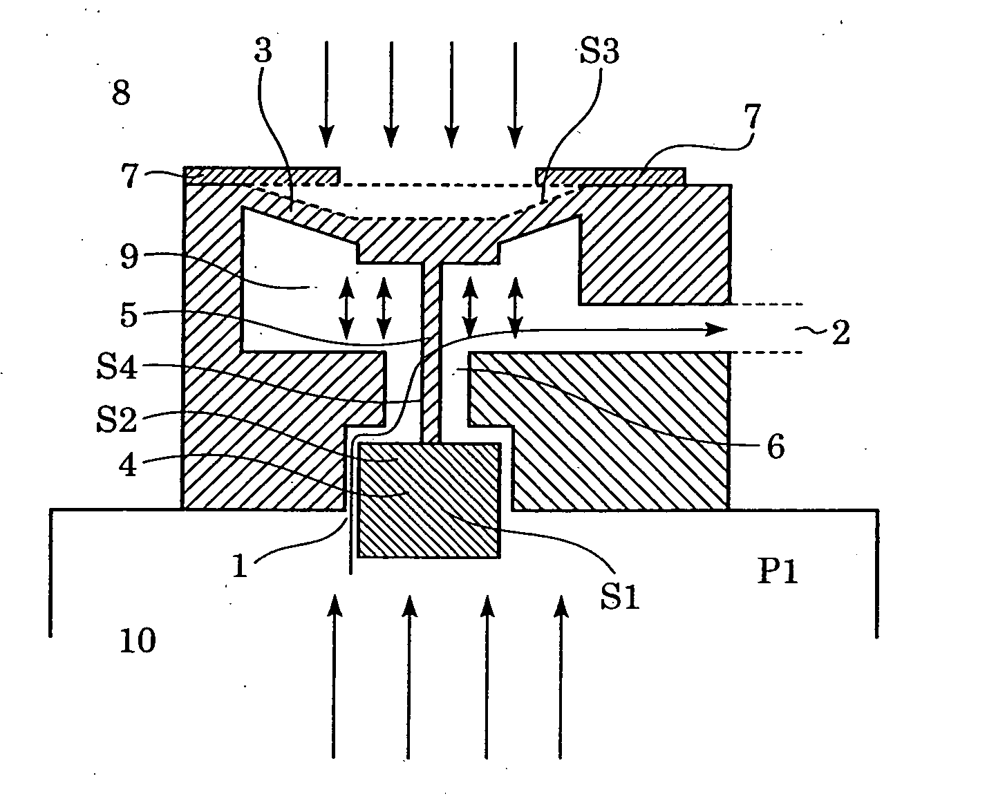
[0055] The valve 18 has the structure as shown in FIG. 12, an outside 23 of a flow path is atmosphere, and a hydrogen gas is allowed to flow through an inside 24 of the flow path. In addition, between the valve portion and the hydrogen storage container 20, a filter 22 is provided so as to prevent a powdered material of the hydrogen absorbing alloy from entering the valve 18.
[0056] According to the structure described above, in normal operation of the fuel cell 17 described above, the pressure regulation is carried out in accordance with the difference in pressure among the air, the hydrogen inside the flow path, and the hydrogen storage container 20. When the concentration of impurity gases in a hydrogen electrode room (not shown) is increased, and the output of the fuel cell is decreased, the valve is forcedly opened using the actuators 7 to supply a highly pressurized hydrogen gas in the hydrogen storage container 20 into the hydrogen electrode room of the power generation portion 19, and the impurity gases are then discharged outside through the exhaust valve 21, so that the inside of the hydrogen electrode room is purged with a hydrogen gas.
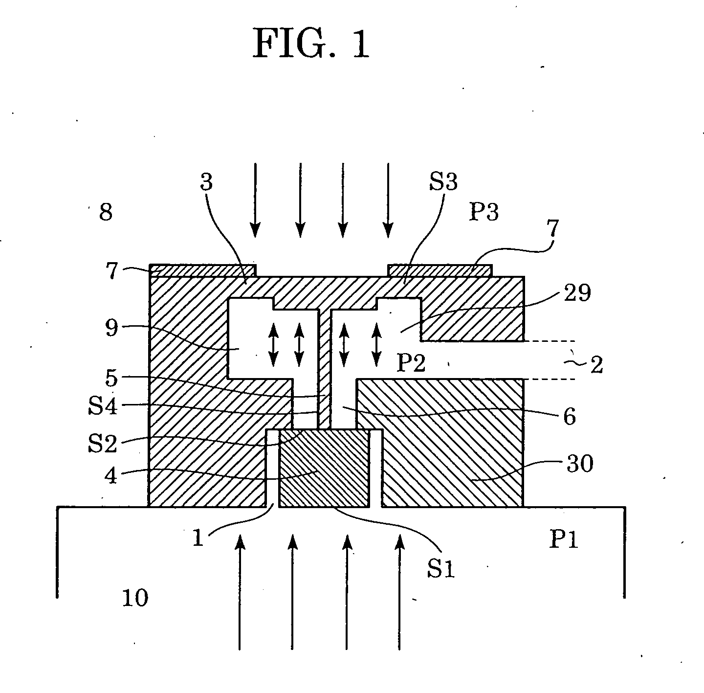
[0057] Hereinafter, the mechanism of the pressure regulation of the fuel cell described above will be described. When the valve is closed as shown in FIG. 12, the relationship represented by the following equation (1) as described above holds, and the pressure P2 of the hydrogen electrode room is maintained at approximately atmospheric pressure.
(P1×S1)+{P2×(S3−S4)}>{P2×(S2−S4)}+(P3×S3) (1)
[0058] However, when the pressure P2 of the hydrogen electrode room is decreased as the hydrogen therein is used for the power generation performed in the fuel cell 17, by the relationship among S1, S2, S3, S4, P1, P2 and P3, a force applied to the diaphragm 3 is increased so as to push the valve element downward, that is, so as to open the valve, and the diaphragm 3 is lowered by x [m] until the following equation (2) as described above holds.
(P1×S1)+{P2×(S3−S4)}+kx{P2×(S1−S4)}+(P3×S3) (2)
Subsequently, a hydrogen gas is again allowed to flow into the hydrogen electrode room from the hydrogen storage container 20, and when the pressure P2 is increased so that the equation (1) holds, the valve is again closed, thereby regulating the pressure of the hydrogen electrode room.
[0059] Next, a purging mechanism will be described. By applying a force represented by the equation (3) described above to the diaphragm using the actuators, a highly pressurized hydrogen gas is supplied into the hydrogen electrode room, and a mixed gas composed of impurity gases and a hydrogen gas is discharged outside through the exhaust valve, thereby performing the purging. In this case, as electricity for driving the actuators, power generation energy of the fuel cell may be used and may be directly supplied therefrom, or in order to prevent an unstable supply of electricity from the fuel cell to a device side, electricity stored beforehand in a capacitor or a secondary cell may be used. In addition, the exhaust valve 21 may be passively opened and closed by the difference in pressure between the hydrogen electrode room and atmospheric pressure, and when a solid polymer membrane is used as an electrolyte of the fuel cell, in consideration of the strength of the membrane, a valve may be used which is opened at a pressure higher than atmospheric pressure by approximately 0.01 to 0.05 MPa.
[0060] In addition, when the temperature of the fuel cell 17 is increased, since the dissociation pressure of a hydrogen absorbing alloy is increased, the pressure P1 of the hydrogen storage container 20 is increased. In this case, even when hydrogen in the hydrogen electrode room is used by the power generation of the fuel cell 17, and the pressure P2 of the hydrogen electrode room is decreased, the valve cannot be passively opened, and as a result, the output of the fuel cell may be decreased in some cases. However, even in the case described above, by the use of the valve 18, when the decrease in output is detected, the valve can be actively opened by using the actuators, and hence shutdown of a device can be prevented which is caused by a large decrease in output.
[0061] In addition to the small fuel cell described above, for example, for a microreactor in which a flow path must be formed in a limited space, the valve of the present invention can be effectively used when purging of a fluid must be performed in a reaction system having one dead end.
[0062] As has thus been described, the valve of the present invention is a valve having a simple structure which can be easily miniaturized and having a pressure regulation mechanism which is unlikely to be degraded even when a corrosive fluid is allowed to flow therethrough. Hence, the valve described above can be applied, for example, to fuel cells, microreactors, and micro total analytical systems (μTAS).
[0063] While the present invention has been described with reference to exemplary embodiments, it is to be understood that the invention is not limited to the disclosed embodiments. On the contrary, the invention is intended to cover various modifications and equivalent arrangements included within the spirit and scope of the appended claims. The scope of the following claims is to be accorded the broadest interpretation so as to encompass all such modifications and equivalent structures and functions.
[0064] This application claims priority from Japanese Patent Application No. 2004-106681 filed Mar. 31, 2004, which is hereby incorporated by reference herein.