Secondary battery having lead plate attached thereto

a lead plate and secondary battery technology, applied in the field of secondary batteries, can solve the problems of potential electric shock, difficult to successfully use ultra-sonic welding or resistance welding on these materials, and difficulty in electrically connecting the electrodes of the bare cell to the electric terminal, and achieves the effect of reliable coupling strength and easy welding

Active Publication Date: 2005-10-06
SAMSUNG SDI CO LTD
View PDF6 Cites 29 Cited by
  • Summary
  • Abstract
  • Description
  • Claims
  • Application Information

AI Technical Summary

Benefits of technology

[0017] A secondary battery is provided having a lead plate attached thereto wherein the bottom portion of the lead plate may be easily welded to a surface of a cap plate for reliable coupling strength between them.
[0018] The secondary battery may further include a cap plate designed such that any floating between the lead plate and the cap plate is prevented.

Problems solved by technology

Generally, it is difficult to electrically connect the electrodes of the bare cell to the electric terminals of, for example, a PCM, by direct welding because of the shape and the material of the bare cell.
However, a problem may occur when trying to weld a lead plate made of nickel to a can made of aluminum.
Because of the high melting points of nickel and aluminum, and the excellent conductivity of aluminum, it is very difficult to successfully use ultra-sonic welding or resistance welding on these materials.
If such laser welding is performed while the lead plate is connected to a protective circuit, the irradiating laser beams may result in potential electric shock or present other safety hazards.
Further, when the lead plate is directly welded to the can, and specifically, to the bottom surface of the can, by laser welding, the electrolyte may leak from the welded portion if the welding strength is not correctly controlled.
This protrusion interferes with the welding and may cause the weld to be weakened.
If welding fails to be correctly performed between the lead plate and the cap plate, the lead plate cannot accomplish the above functions.
As a result, the mechanical strength or the electric connection of a finished secondary battery deteriorates.

Method used


Image

  • Secondary battery having lead plate attached thereto
  • Secondary battery having lead plate attached thereto
  • Secondary battery having lead plate attached thereto

Examples


Embodiment Construction

[0025] Hereinafter, exemplary embodiments of the present invention will be described with reference to the accompanying drawings. In the following description and drawings, the same reference numerals are used to designate the same or similar components.

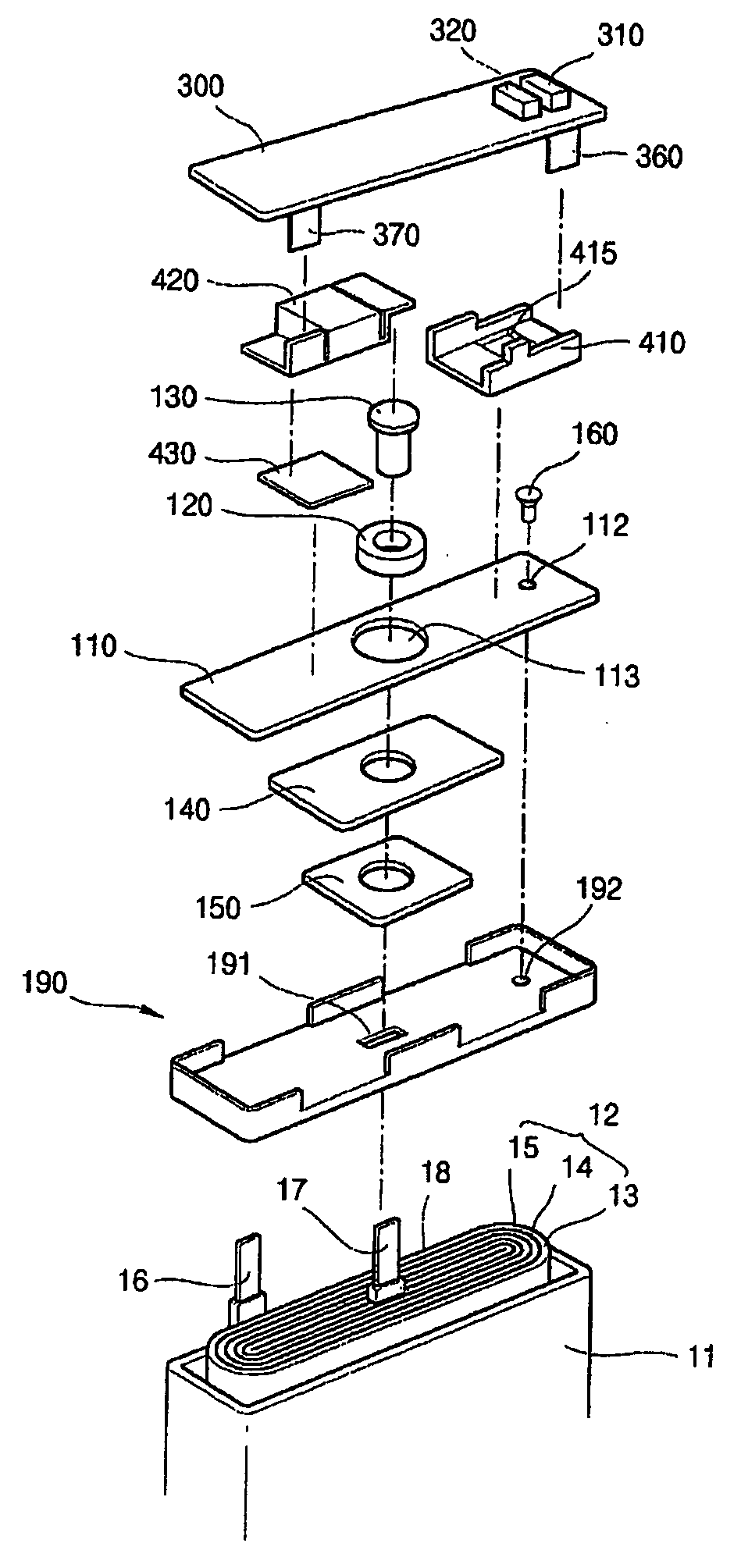
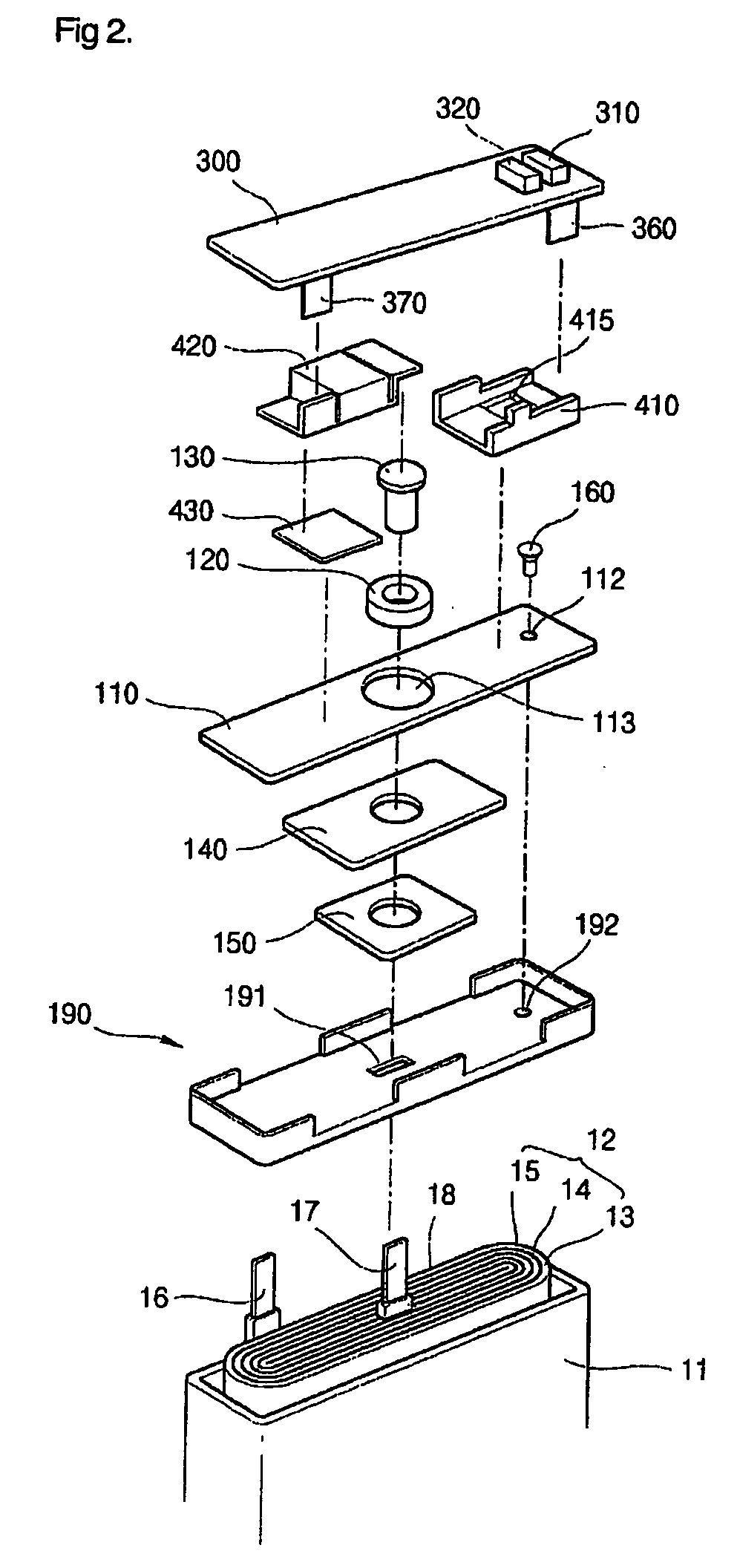
[0026] Referring now to FIG. 2, a lithium pack battery has a bare cell which includes a can 11, a electrode assembly 12 contained in the can 11, and a cap assembly coupled to the open upper end of the can 11 for sealing it.

[0027] The electrode assembly 12 is formed by winding a positive electrode 13, a separator 14, and a negative electrode 15, which are formed in a thin plate shape, a film shape or an eddy shape. Insulating tape 18 is wound about respective boundary portions wherein positive and negative leads 16 and 17 are led out of the electrode assembly 12 in order to prevent a short circuit between the two electrodes 13 and 15. The can 11 is generally made of aluminum or an aluminum alloy having the shape of a cuboid. The can...


PUM

PropertyMeasurementUnit
thicknessaaaaaaaaaa
thicknessaaaaaaaaaa
thicknessaaaaaaaaaa

Abstract

A secondary battery comprises a bare cell including an electrode assembly composed of positive and negative electrodes and a separator, a can acting as a container for containing the electrode assembly and an electrolyte, and a cap assembly having a cap plate for covering the open upper end of the can and a lead plate coupled to a part of the cap plate, wherein an electrolyte injection hole is positioned on a side of the cap plate. The lead plate has a bottom portion which covers the electrolyte injection hole and at least a part of which is coupled to a surface of the cap plate. Additionally, a part of the lead plate, which corresponds to the electrolyte injection hole of the bottom portion, is removed to form a hole so that a cap which seals the electrolyte injection hole is exposed.

Description

CROSS-REFERENCE TO RELATED APPLICATION(S) [0001] This application claims priority to and the benefit of Korean Patent Application number 2004-21428, filed Mar. 30, 2004, the entire disclosure of which is incorporated herein by reference. BACKGROUND OF THE INVENTION [0002] 1. Field of the Invention [0003] The present invention relates to a secondary battery, and more particularly to a secondary battery having a lead plate attached thereto. [0004] 2. Description of the Prior Art [0005] Recently, secondary batteries have been developed and used extensively because they are rechargeable and have the potential to be compact, yet have a large capacity. Typical examples of secondary batteries include nickel-metal hydride (Ni-MH) batteries, lithium (Li) batteries, and lithium ion batteries. [0006] In most cases, the bare cell of secondary batteries is formed by placing an electrode assembly, composed of positive and negative electrodes and a separator, into a can which is made of iron, alum...

Claims


Application Information

Patent Timeline
Patent Type & Authority Applications(United States)
IPC IPC(8): H01M2/02H01M2/20H01M10/00H01M10/04H01M2/08H01M2/04H01M2/06H01M2/36H01M2/26H01M2/34H01M2/30H01M10/40H01M10/38H01M10/05H01M50/531H01M50/645
CPCH01M2/0217H01M2/26H01M2/361H01M2/365H01M10/0436H01M10/052Y10T29/49114Y02E60/10H01M50/103H01M50/531Y02P70/50H01M50/645
Inventor YOON, HEUI SANG
Owner SAMSUNG SDI CO LTD
Why Eureka
Try Eureka