Enhanced burner performance gas range system and method

a burner performance and gas range technology, applied in the field of gas range systems, can solve the problems of not being able to achieve the desired degree of primary entrainment, limiting secondary entrainment and flame length, and not being able to achieve the enhancement required to operate within the industry standards for emissions and fabric ignition

Inactive Publication Date: 2005-10-06
GENERAL ELECTRIC CO
View PDF10 Cites 20 Cited by
  • Summary
  • Abstract
  • Description
  • Claims
  • Application Information

AI Technical Summary

Benefits of technology

[0008] Briefly, in accordance with one aspect of the present invention an enhanced gas range system includes a pressure regulator adapted to regulate a gas flow from a gas feed line. The system also includes a gas fuel boost pump disposed downstream of the pressure regulator and adapted to increase pressure of the gas flow received from the gas feed line. A gas burner is disposed to receive the gas flow from the gas fuel boost pump.

Problems solved by technology

However, while certain gas range systems using these techniques may provide increased primary air entrainment, they may not affect enough enhancement to operate within the industry standards for emissions and fabric ignition.
That is, existing systems may not provide the desired degree of primary entrainment to support the combustion of higher fuel flow rates, while limiting secondary entrainment and flame lengths.
In general, these primary entrainment enhancement concepts are not configured to prevent a condition wherein the mechanism for augmenting primary aeration fails while fuel continues to flow at a high rate, thereby not satisfying the industry standards with respect to emissions and fabric ignition.
While such control mechanisms for the gas range system have proven valuable in enhancing the burner performance by utilizing the inputs from the user and the measurement of the existing gas flow, the control is limited to enhancing the burner output using the existing feed pressure of the gas from the gas feed line, thereby limiting the peak burner output value through primary air entrainment.

Method used


Image

  • Enhanced burner performance gas range system and method
  • Enhanced burner performance gas range system and method
  • Enhanced burner performance gas range system and method

Examples


Embodiment Construction

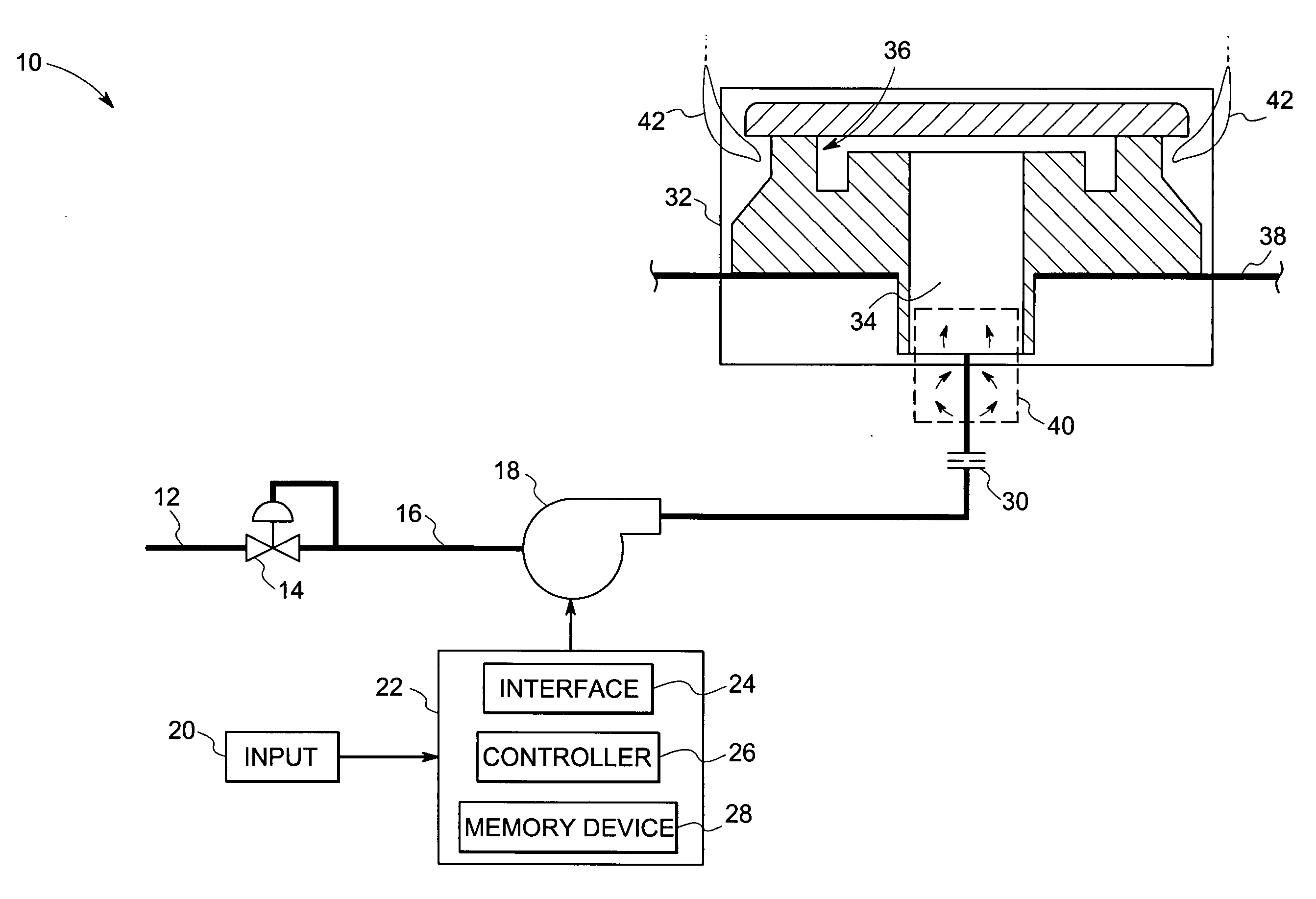
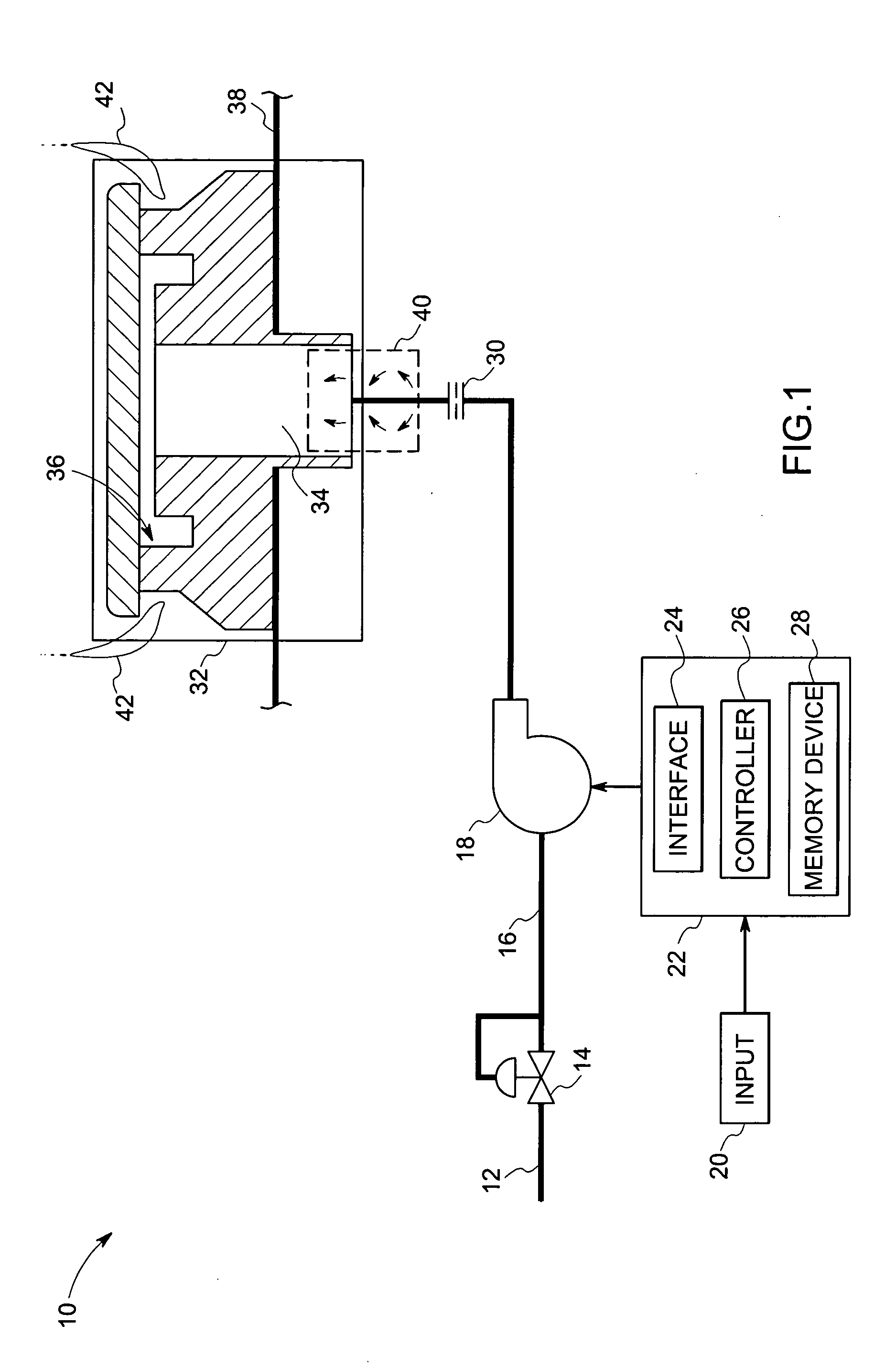
[0016]FIG. 1 illustrates a gas range system 10, according to an embodiment, for use in a gas operated cooking appliance, such as, but not limited to, gas stove, gas cookers, gas hobs, and gas ovens. In the embodiment illustrated in FIG. 1, gas range system 10 receives a supply of combustible gas from a supply line 12 via a pressure regulator 14. A conduit, such as tubing 16 then delivers the pressure regulated gas to a gas fuel boost pump 18 located downstream of the pressure regulator 14. As described in greater detail below, based upon user-defined inputs 20, flow control circuitry 22 coupled to the gas fuel boost pump 18 regulates the gas flow through the gas fuel boost pump 18. In operation, the gas range system 10 receives a gas flow from a supply, for example, a gas supply network, gas cylinder, gas tank and so forth.

[0017] Typically, the gas flow is received from the supply device at the natural gas supply pressure that may be about 5 to 10 inches of water column. This flow ...


PUM


Abstract

An enhanced gas range system includes a pressure regulator adapted to regulate a gas flow from a gas feed line. The system also includes a gas fuel boost pump disposed downstream of the pressure regulator and adapted to increase pressure of the gas flow received from the gas feed line. A gas burner is disposed to receive the gas flow from the gas fuel boost pump.

Description

BACKGROUND [0001] The invention relates generally to a gas range system and more particularly, to enhancement of burner performance of a gas range system for a cooking appliance. [0002] Conventional gas operated cooking appliances, for example gas cooktops, have one or more burners, in which gas is mixed with air and burned. The burner typically comprises an orifice and venturi assembly for the entrainment of air by mixing air with the gas required to generate the burner power output. The process of drawing air into the gas stream, upstream of the burner is sometimes referred to as “primary entrainment.” The gas is extracted from a supply device, for example a gas supply network and fed to a burner via a gas feed line. In conventional systems, the gas is supplied at a pressure of the natural gas supply source. This flow of the gas is then mixed with air in the venturi assembly, which provides the primary aeration of the burner. [0003] Further, the burner also comprises multiple burn...

Claims


Application Information

Patent Timeline
Patent Type & Authority Applications(United States)
IPC IPC(8): F23D14/04F23D14/34F23M3/00F23N1/00F23N5/20F24C3/12
CPCF23D14/04F23D14/34F23N1/002F23N5/203F23N2023/04F23N2023/08F23N2025/06F23N2037/02F24C3/126F23N2223/04F23N2223/08F23N2225/06F23N2237/02
Inventor NAJEWICZ, DAVID JOSEPHHIBSHMAN, JOELL RANDOLPH IILYER, VENKATRAMAN ANANTHAKRISHNAN
Owner GENERAL ELECTRIC CO
Why Eureka
Try Eureka