Dual conversion receiver with reduced harmonic interference

a conversion receiver and harmonic interference technology, applied in the direction of radio transmission, transmission, electrical equipment, etc., can solve the problems of unwanted harmonic interference, mixing of the first and second local oscillators,

Inactive Publication Date: 2005-10-06
AVAGO TECH INT SALES PTE LTD
View PDF22 Cites 32 Cited by
  • Summary
  • Abstract
  • Description
  • Claims
  • Application Information

AI Technical Summary

Benefits of technology

[0013] Specifically, in one embodiment, the frequency step size of the first local oscillator signal is determined so that the spurious signal represented by |2·LO1−3·LO2|, does not interfere with the desired channel at the second IF frequency (IF2), where 2·LO1 represents the second harmonic of the first local oscillator signal, and 3·LO2 represents the third harmonic of the second local oscillator signal. Even more specifically, the frequency step size of the first local oscillator is set to 10.35 MHz so as to avoid spurious signal interference for a 36 MHz or a 44 MHz second IF signal.

Problems solved by technology

One problem with dual conversion tuners, is that harmonics of the first and second local oscillators can mix, for example in the second mixer stage, and fall in the passband of the baseband SAW filter.
When this occurs, the unwanted harmonics can interfere with the down-converted channel.

Method used


Image

  • Dual conversion receiver with reduced harmonic interference
  • Dual conversion receiver with reduced harmonic interference
  • Dual conversion receiver with reduced harmonic interference

Examples


Embodiment Construction

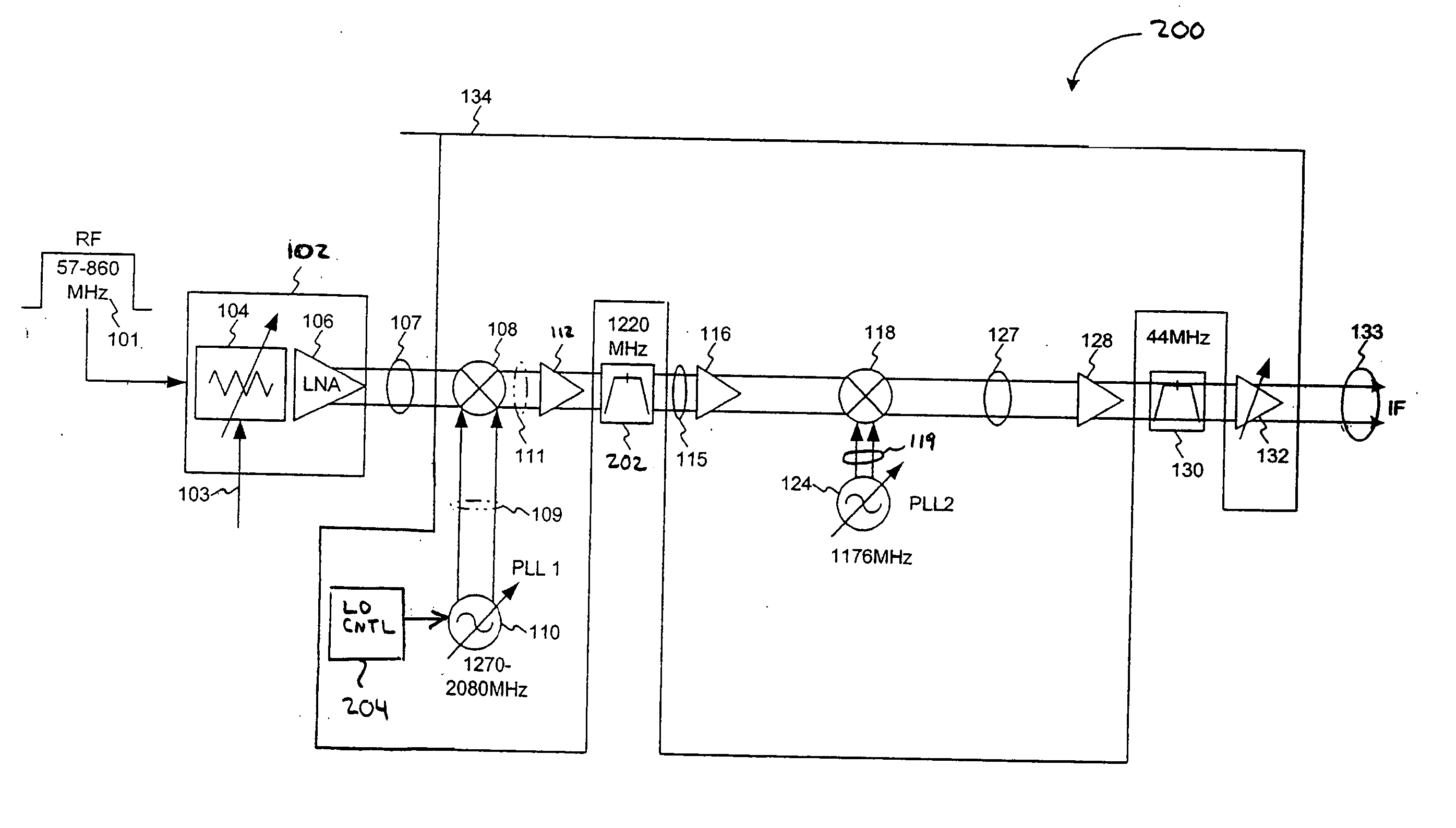
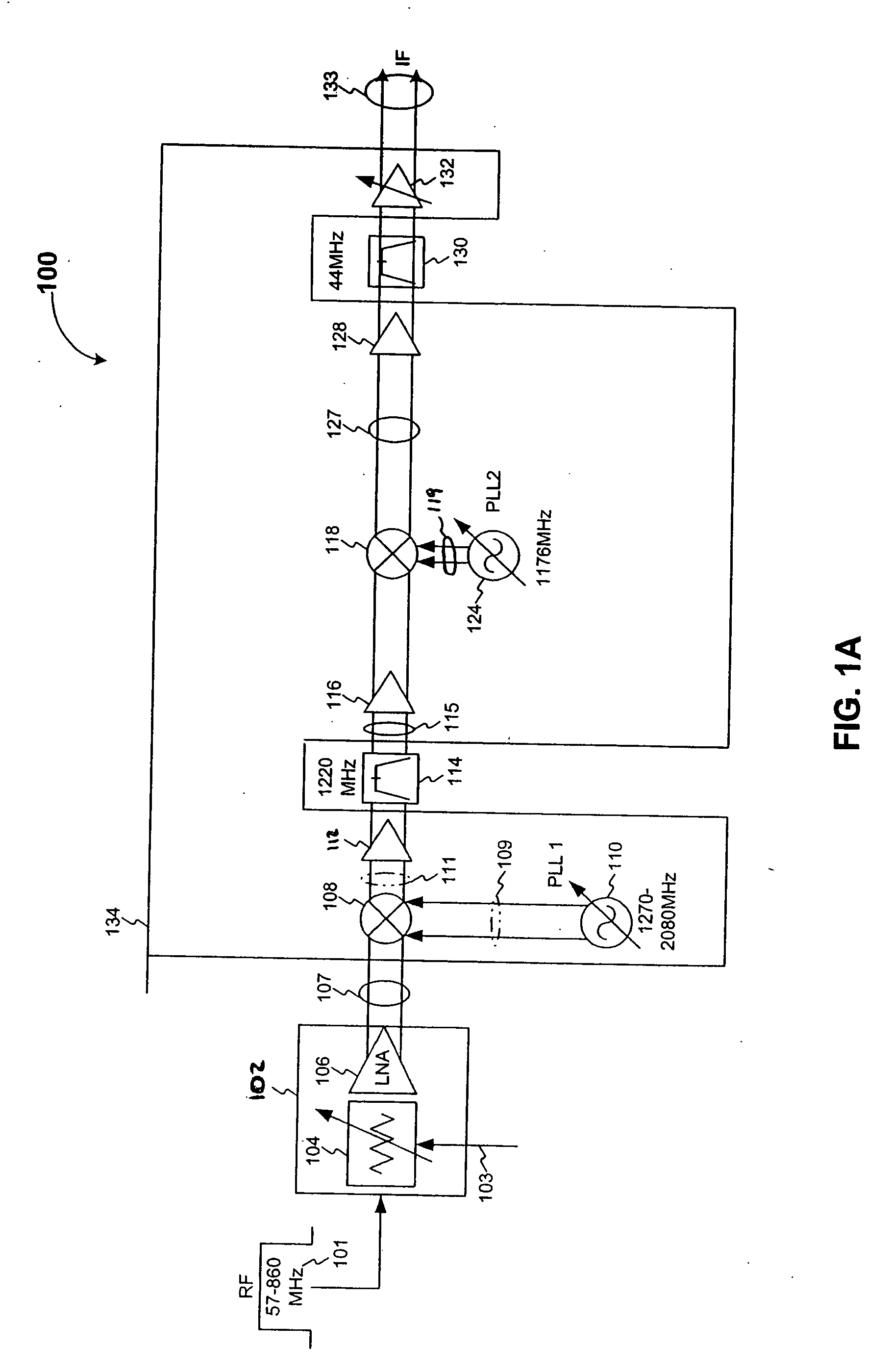
[0019]FIG. 1A illustrates a schematic of a tuner assembly 100 that has an automatic gain control circuit (AGC) 102 and a tuner 134.

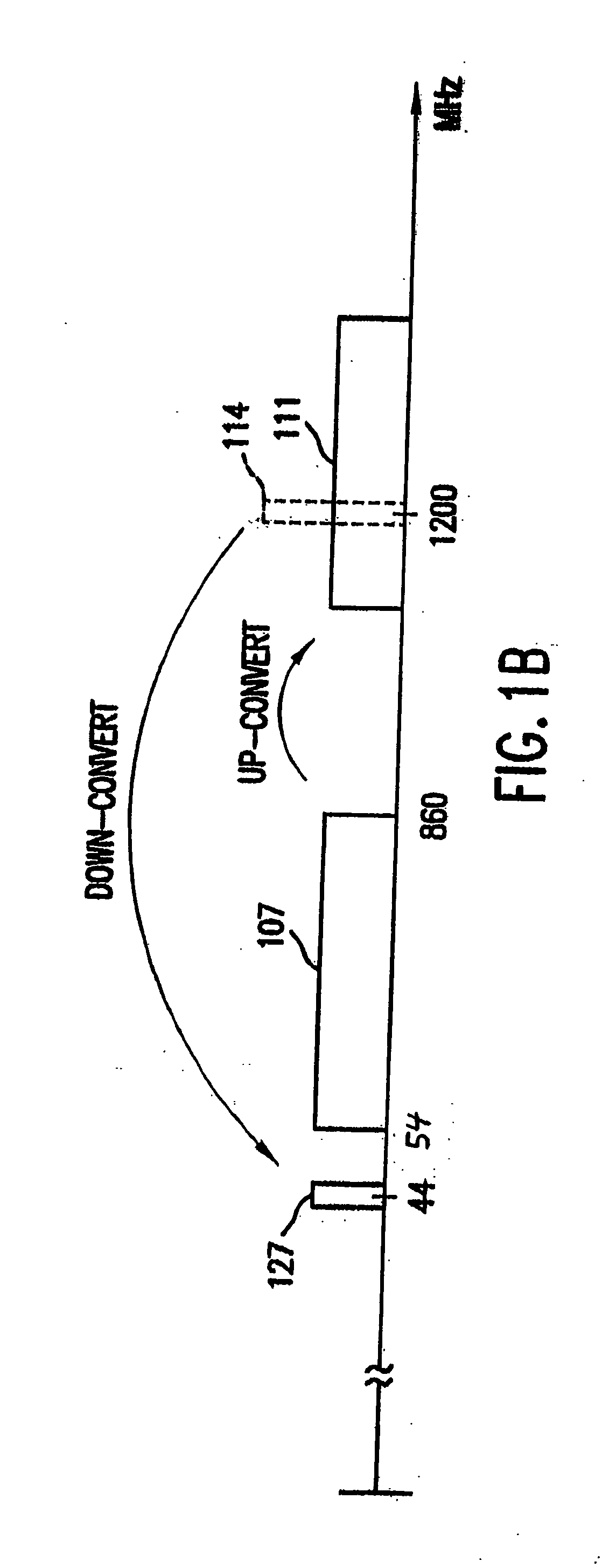
[0020] The tuner assembly 100 receives an RF input signal 101 having multiple channels and down-converts a selected channel to an IF frequency, to produce an IF signal 133. For instance, the RF input signal 101 can include multiple TV channels that typically have 6 MHZ frequency spacings and cover a range of 54-860 MHZ, and where the selected channel is down-converted to an IF frequency at 44 MHZ, 36 MHZ or some other desired IF frequency for further processing. The frequencies listed herein are not meant as a limitation and are provided for example purposes only. The structure and operation of the tuner assembly 100 are described in further detail below.

[0021] The AGC circuit 102 provides automatic gain control using a variable resistor104 and a low noise amplifier (LNA) 106. The variable resistor 104 attenuates the RF input signal 101 according to a ...


PUM


Abstract

A dual conversion receiver selects and down-converts one channel from a plurality of channels in a received RF signal. The dual conversion receiver includes first and second mixer stages that are driven by first and second local oscillator signals. Channel selection is performed by tuning the first local oscillator signal so that a desired channel is up-converted to a first IF frequency, which defines the center of the passband of a first bandpass filter connected between the first and second mixer stages. The second mixer stage down-converts the output of the first bandpass filter to a second IF frequency, which is further filtered by a second bandpass filter. The first and second local oscillators can produce harmonics that mix in the second mixer stage, causing unwanted spurious signals that can fall in band with the second IF frequency. In order to avoid interference from these unwanted spurious signals, the frequency step size of the first local oscillator is tuned so that the spurious signals fall out-of-band of the second IF frequency.

Description

CROSS REFERENCED TO RELATED APPLICATIONS [0001] This application claims the benefit of U.S. Provisional Application No. 60 / 558,545, filed on Apr. 2, 2004, which is incorporated by reference herein in its entirety.BACKGROUND OF THE INVENTION [0002] 1. Field of the Invention [0003] The present invention generally relates to reducing harmonic interference from local oscillators in a dual conversion receiver. [0004] 2. Background Art [0005] Television signals are transmitted at radio frequencies (RF) using terrestrial, cable, or satellite transmission schemes. Terrestrial and cable TV signals are typically transmitted at frequencies of approximately 57 to 860 MHZ, with 6 MHZ channel spacings in the United States and 8 MHz channel spacing in Europe. Satellite TV signals are typically transmitted at frequencies of approximately 980 to 2180 MHz. [0006] Regardless of the transmission scheme, a tuner is utilized to select and down-convert a desired channel from the TV signal to an intermedia...

Claims


Application Information

Patent Timeline
Patent Type & Authority Applications(United States)
IPC IPC(8): H04B1/26H04B1/28H04B1/40H04B15/00
CPCH04B1/28
Inventor GOMEZ, RAMON A.WAKAYAMA, MYLES
Owner AVAGO TECH INT SALES PTE LTD
Why Eureka
Try Eureka