Process for producing phenol

a technology of phenol and acetone, which is applied in the field of producing a phenol stream, can solve the problems of reducing the quality of phenol products, reducing the efficiency of phenol production,

Inactive Publication Date: 2005-10-06
SABIC GLOBAL TECH BV
View PDF36 Cites 14 Cited by
  • Summary
  • Abstract
  • Description
  • Claims
  • Application Information

AI Technical Summary

Benefits of technology

[0012] In one embodiment, a process for producing a phenol product comprises a first step comprising reacting in a first reactor a feed stream comprising cumene hydroperoxide and water with an acid catalyst to produce an effluent comprising the phenol product, acetone, and at least 1% by weight residual cumene hydroperoxide, and a second step comprising passing the effluent into a second reactor and decomposing the residual cumene hydroperoxide, wherein during said process the ratio of phenol to acetone is maintained at a molar ratio of greater than 1:1, and wherein the water in each of the first and second steps is present in an amount more than 0 and less than or equal to 5 weight percent based on the total weight of the feed stream or effluent, and wherein the process is continuous.
[0013] In another em

Problems solved by technology

Although extra acetone addition can be an effective method for inhibiting the CHP decomposition reaction and enhancing DCP formation, such a cleavage process operating with a high acetone:phenol ratio is subject to the disadvantage of forming increased levels of other harmful “carbonyl-type” by-products such as hydroxyacetone (also known as HA or acetol) and mesityl oxide (MO).
Moreover, as a result of the carbonyl impurities formed during cleavage, the resulting phenol and acetone products have to be separated from these undesirable by-products and impurities using energy intensive processes.
For example, the presence of acetol impurities in the phenol product renders quality unacceptable for many end-use applications, such a

Method used


Image

  • Process for producing phenol

Examples


examples

[0036] In these Examples, the analysis of hydroxyacetone was carried out on an Agilent 6890 Gas chromatograph (GC). GC separation was carried out on glass column with a length 24 inches &¼ inch outer diameter, configured for on column injection, packed with chromsorb 102 80 / 100 mesh, with helium as carrier gas at 30 milliliters per minute (ml / min). The injector temperature was maintained at 160° C. and the detector temperature was maintained at 250° C. The initial column temperature was kept at 110° C. for 3 minutes hold time, this was followed by a temperature increase at 7° C. per minute to reach 150° C., held for 2 minutes, at 150° C., followed by a temperature increase at 10° C. per minute to reach 200° C. and held at 200° C. for 15 minutes. The column was calibrated with standard hydroxyacetone (obtained from Aldrich Chemical Company, 97% pure) at a concentration ranging from 5 parts per million (ppm) to 244 ppm made in a 50:50 mixture of cumene and phenol. Hydroxyacetone in th...

examples 1-3

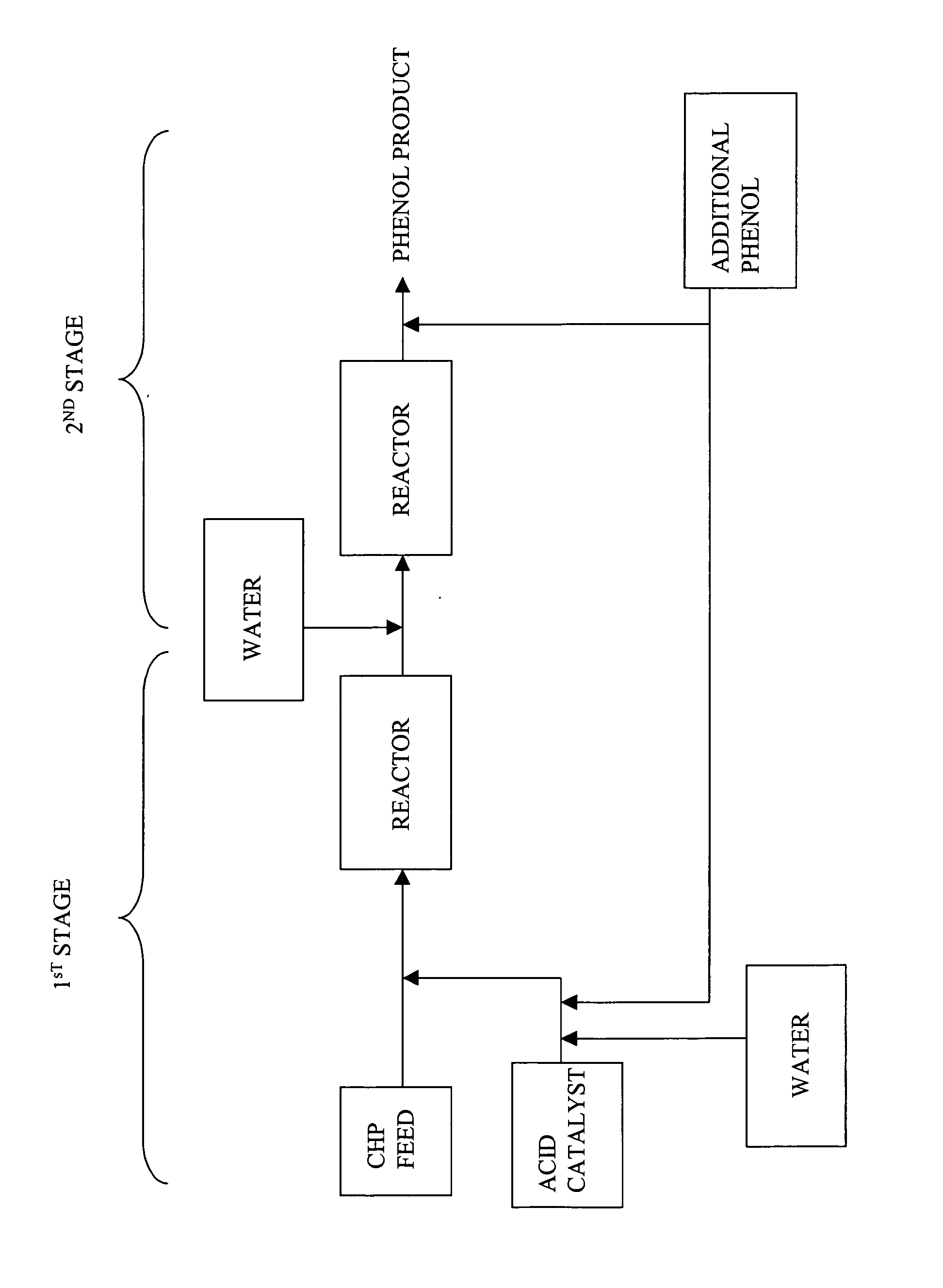
[0042] In these examples, CHP was decomposed in a continuous 2-STEP process to obtain a phenol product, wherein the molar ratio of phenol to acetone was greater than or equal to 1.2:1, and the effluent produced from the first step contained at least 1% residual CHP. Table 3 illustrates the composition of the feed stream. The process generally included adding CHP to an agitated mixture of phenol, acetone, and sulfuric acid.

[0043] In the first step of the continuous process, a typical synthetic feed composition having phenol, acetone, and CHP was fed to a glass reactor fitted with a condenser having a capacity of about 150 milliliters through the respective inlets for the feed stream and acid catalyst. The reactor was also fitted with a temperature probe to monitor the temperature and external heating / cooling jacket to maintain the temperature. The contents of the reactor were continuously stirred with a magnetic stirrer. The composition of the feed stream and amount of catalyst adde...


PUM

PropertyMeasurementUnit
Temperatureaaaaaaaaaa

Abstract

A process for producing a phenol product generally comprises a first step comprising reacting in a first reactor a feed stream comprising cumene hydroperoxide and water with an acid catalyst to produce an effluent comprising the phenol product, acetone, and at least 1% by weight residual cumene hydroperoxide, and a second step comprising passing the effluent into a second reactor and decomposing the residual cumene hydroperoxide, wherein during said process the ratio of phenol to acetone is maintained at a molar ratio of greater than 1:1, and wherein the water in each of the first and second steps is present in an amount more than 0 and less than or equal to 5 weight percent based on the total weight of the feed stream or effluent, and wherein the process is continuous.

Description

CROSS REFERENCE TO RELATED APPLICATIONS [0001] The present application is a continuation-in-part application of and claims priority to, U.S. patent application Ser. No. 10 / 815,575 filed on Mar. 31, 2004, incorporated herein by reference in its entiretyBACKGROUND [0002] The present disclosure generally relates to a method for producing a phenol stream with reduced by-products. More particularly the present invention relates to a two-step continuous method for producing a phenol stream with reduced by-products. [0003] The cleavage reaction of cumene hydroperoxide (CHP) in the manufacture of phenol and acetone from cumene is well known. Today most modern CHP cleavage processes are carried out in a continuous flow manner and utilize the so-called “2-stage cleavage process”, which provides the best economics because, in addition to making phenol and acetone from CHP, it recovers cumene value from the by-product DMBA formed in the prior cumene oxidation step. Such prior art 2-stage cleava...

Claims


Application Information

Patent Timeline
IPC IPC(8): C07C37/08C07C39/04
CPCC07C37/08C07C39/04
Inventor TATAKE, PRASHANT ANILKUMBHAR, PRAMOD SHANKARSINGH, BHARATFULMER, JOHN WILLIAMMANDAL, SABYASACHIKUMAR, ARUN N.PAWAR, RUPESH
Owner SABIC GLOBAL TECH BV
Why Eureka
Try Eureka