Automatic detection system for broken tools in CNC machining centers using advanced machine vision techniques

a technology of automatic detection and machine vision, applied in the direction of manufacturing tools, metal-working machine components, instruments, etc., can solve the problems of unreliable attempts, unreliable 100 percent manual inspection, and failure to maintain, so as to prevent damage to subsequent components

Active Publication Date: 2005-10-06
BUDD GERALD WALTER
View PDF8 Cites 33 Cited by
  • Summary
  • Abstract
  • Description
  • Claims
  • Application Information

AI Technical Summary

Benefits of technology

[0007] The invention describes a method for the inspection of machining tools used in computational numerical control (CNC) machining centers. The invention will observe a machining tool immediately after use to determine if it has been damaged. The invention is based on a machine vision technology that uses one or more image sensors to acquire, locate and compare the tool to a good model. The inspection equipment is designed for implementation in the CNC automatic tool changing system and will alert the operator that tool has been damaged before the next operation. This immediate response of the invention will contain defect components and prevent damage to subsequent components. With the addition of an infrared image sensor the invention is capable of detecting worn or dull tools that may damage a component due to excessive heating.

Problems solved by technology

One hundred percent manual (human) inspection is only 80 percent reliable, per automotive supplier quality specialists.
A major drawback with the use of automatic tool changing technology is that fact that a machine will continue to function with a defective tool.
However the attempts have proven to be unreliable and difficult to maintain.
Laser detectors, photoelectric detectors and mechanical probe fail to detect defective tools when they are chipped or cracked.
Motor torque monitors usually detect only catastrophic modes of tool failures.
CCD camera technology has been applied to tool setup but has been limited to off-line applications only.

Method used


Image

  • Automatic detection system for broken tools in CNC machining centers using advanced machine vision techniques
  • Automatic detection system for broken tools in CNC machining centers using advanced machine vision techniques
  • Automatic detection system for broken tools in CNC machining centers using advanced machine vision techniques

Examples


Embodiment Construction

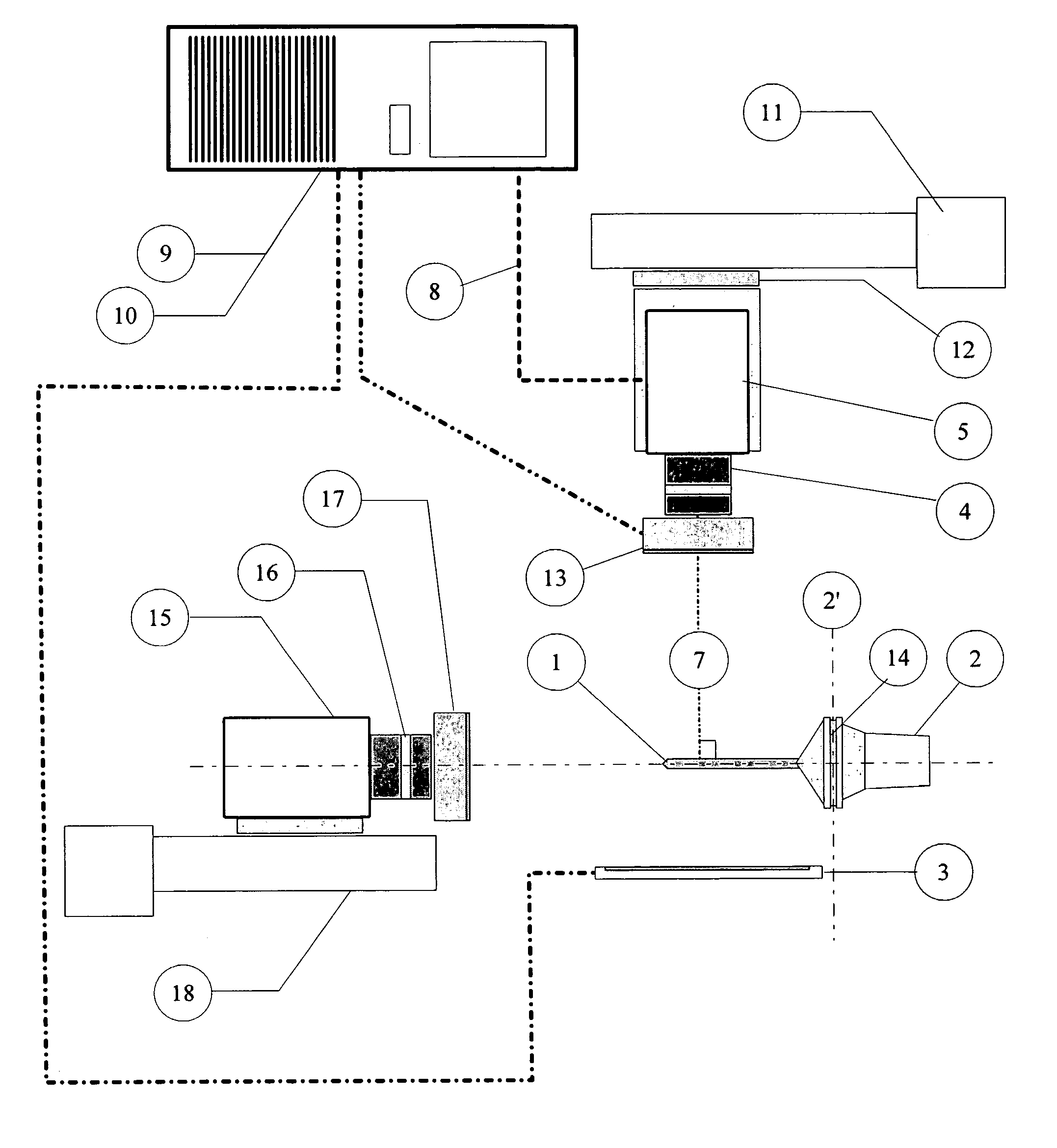
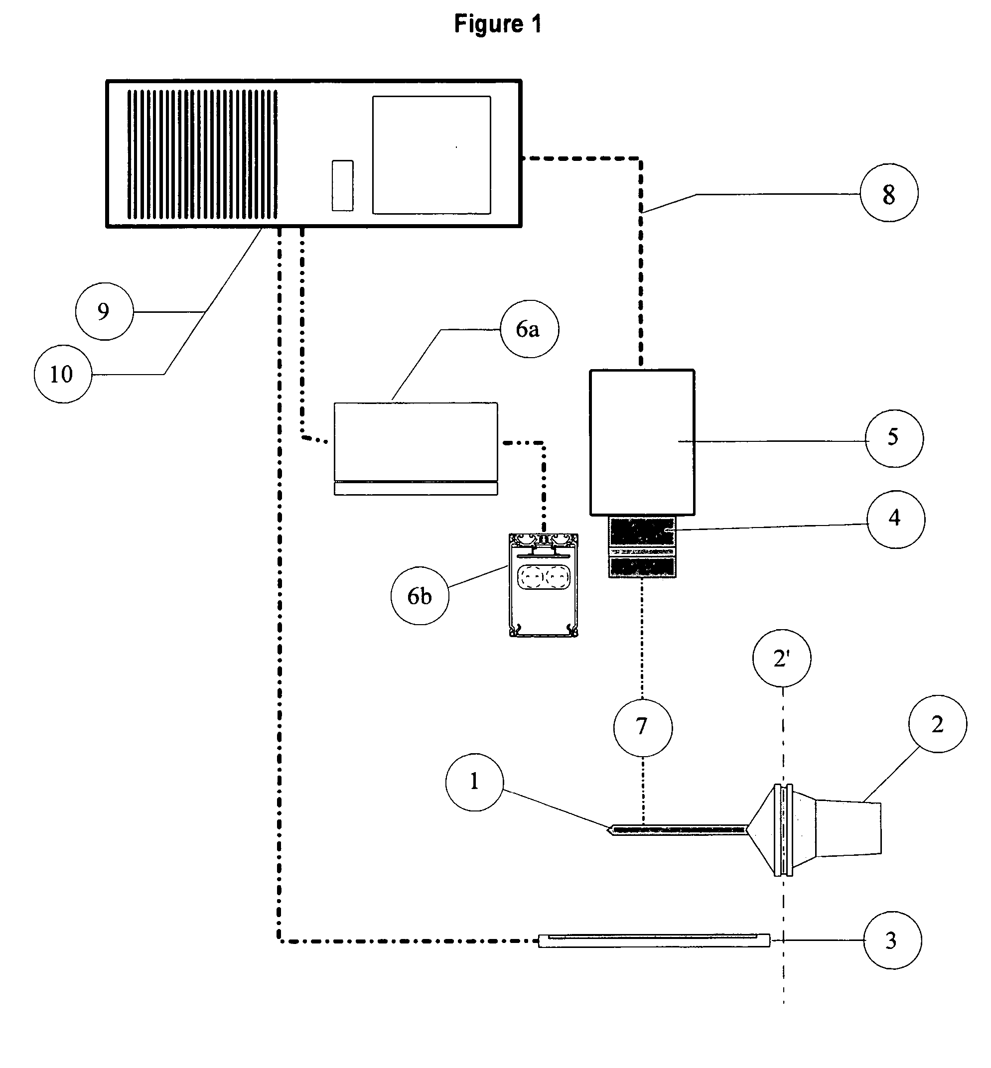
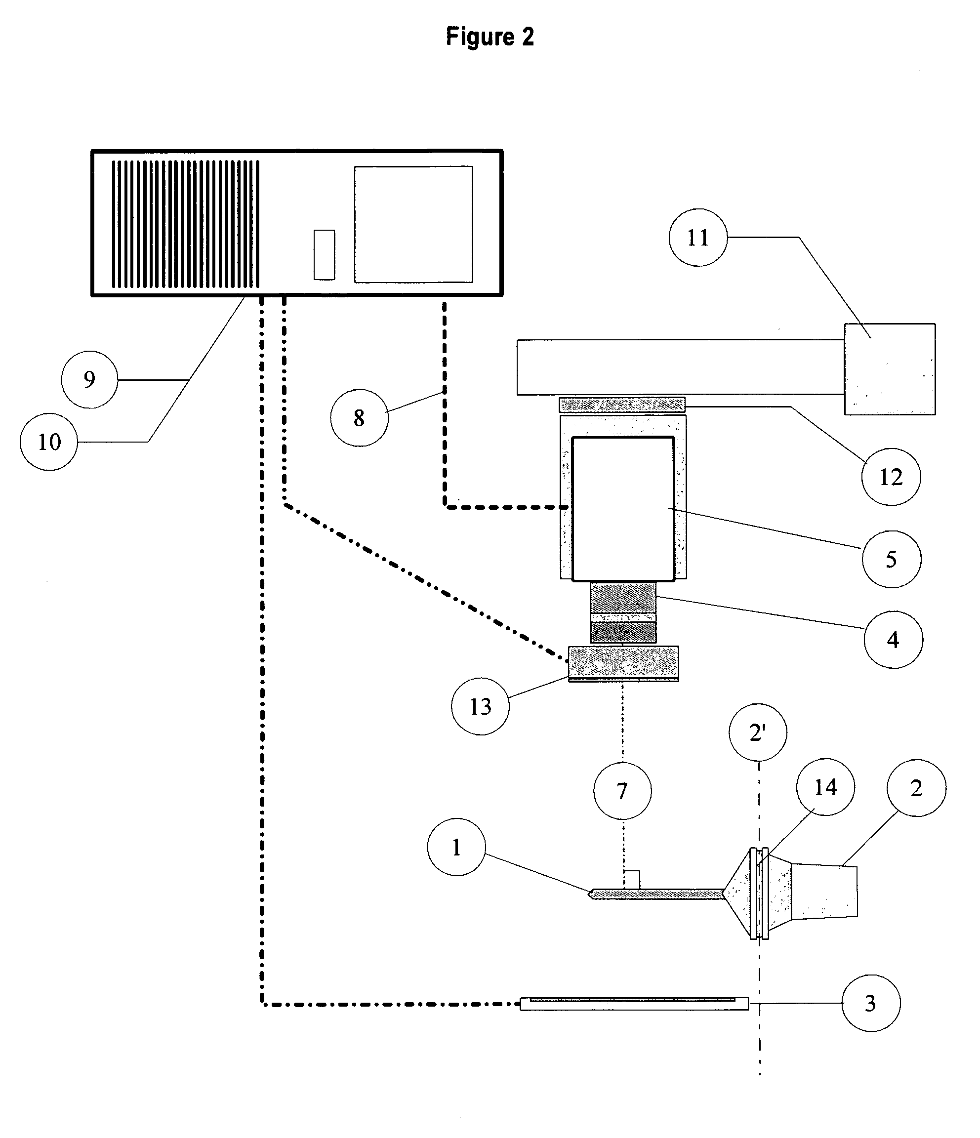
[0033] This invention has application in all high volume / high speed CNC machining centers with an automatic tool changer used in modern manufacturing facilities. The present invention is referred to as the Broken Tool Detection System (BTDS) and is designed for operation on the equipment of all major suppliers of CNC machining centers.

[0034] The basic BTDS is a combination of four key components configured in the proper way to determine if machining tools are physically damaged immediately after use and require replacement prior to continuing operation. The key components are an illumination module, one or more sensor module(s), and one or more image processing systems and application specific software used to determine the condition of the machining tools.

[0035] In its most primitive form, the BTDS will use a single sensor to determine the condition of a simple geometry tool, such as a drill, tap or reamer. The advantage that this system has over competitive technologies is that ...


PUM


Abstract

The invention describes a method for the inspection of machining tools used in computational numerical control (CNC) machining centers. The invention will observe a machining tool immediately after use to determine if it has been damaged. The invention is based on a machine vision technology that uses one or more image sensors to acquire, locate and compare the tool to a good model. The inspection equipment is designed for implementation in the CNC automatic tool changing system and will alert the operator that tool has been damaged before the next operation. This immediate response of the invention will contain defect components and prevent damage to subsequent components. With the addition of an infrared image sensor the invention is capable of detecting worn or dull tools that may damage a component due to excessive heating.

Description

CROSS-REFERENCE TO RELATED APPLICATIONS [0001] I claim priority to my Provisional Application No. 60 / 558,897 with filing date Apr. 3, 2004.FIELD OF THE INVENTION [0002] This invention relates to the procedures and devices utilized in the inspection of machining tools used in computational numerical control (CNC) machining centers and as an aid for the setup of the machining tools. BACKGROUND OF THE INVENTION [0003] The CNC machining center technology used today has increased the production of complex components significantly. The CNC machining centers can perform 5 and 6 axis operations a very high speed. One of the most important improvements made to the technology in recent years is the automatic tool changing system. This system allows the CNC machining center to retrieve a specific tool for each operation without intervention from an operator. The advent of this technology allows one operator to setup and service several CNC machining centers, thus reducing plant operational cos...

Claims


Application Information

Patent Timeline
Patent Type & Authority Applications(United States)
IPC IPC(8): G06F19/00
CPCB23Q17/0909B23Q17/2457G01B11/2433
Inventor BUDD, GERALD WALTER
Owner BUDD GERALD WALTER
Why Eureka
Try Eureka