Assessment and optimization for metrology instrument

a metrology instrument and optimization technology, applied in the field of metalrology instruments, can solve the problems of inability to widely accept the standards relative to the required parameters, difficulty in correct assessment and optimization of inability to accurately assess and optimize the measurement potential of the metrology instrumen

Inactive Publication Date: 2005-10-06
INT BUSINESS MASCH CORP
View PDF3 Cites 8 Cited by
  • Summary
  • Abstract
  • Description
  • Claims
  • Application Information

AI Technical Summary

Problems solved by technology

Unfortunately, correctly assessing and optimizing the measurement potential of a metrology instrument is difficult for a number of reasons.
For example, an evaluator normally has limited access to the various instruments under consideration.
Finally, there are no widely accepted standards relative to the required parameters and how the parameters should be measured.
As a result, an adequate solution for calculating an uncertainty of a metrology instrument in meaningful units of length for comparison to manufacturing lithography requirements has been elusive.
Unfortunately, the repeatability and reproducibility of a measurement is meaningless if the measurement is wrong.
The above-described methods do not evaluate the accuracy of an instrument apart from ensuring proper magnification by calibration with pitch standards.
The reason, in part, that accuracy is not considered is that accepted accuracy standards are generally not available because the speed at which semiconductor technology advances usually makes any standard obsolete very quickly.

Method used


Image

  • Assessment and optimization for metrology instrument
  • Assessment and optimization for metrology instrument
  • Assessment and optimization for metrology instrument

Examples


optimization example

[0062] Referring to FIG. 8, an example derived from optimizing measurement conditions on a CDSEM for a resist isolated line geometry is graphically illustrated. The CD SEM starting conditions were those of one of the CD SEMs discussed earlier. While several acquisition conditions and algorithms settings were optimized in this investigation, the graph shown in FIG. 8 illustrates the consequences of changing the amount of smoothing done to the raw CD SEM waveform prior to further algorithm analysis. In particular, the noise reduction from this smoothing has a positive effect upon reducing the corrected precision. However, from the point of view of TMU, the trend is opposite. This suggests that the loss of accuracy in tracking the process changes in the artifact is worse with greater smoothing as evidenced by this trend dominating the TMU.

[0063] IV. Conclusion

[0064] Although particular embodiments of assessment and optimization methods have been described above, it should be recogniz...


PUM

PropertyMeasurementUnit
net residual erroraaaaaaaaaa
widthaaaaaaaaaa
depthaaaaaaaaaa

Abstract

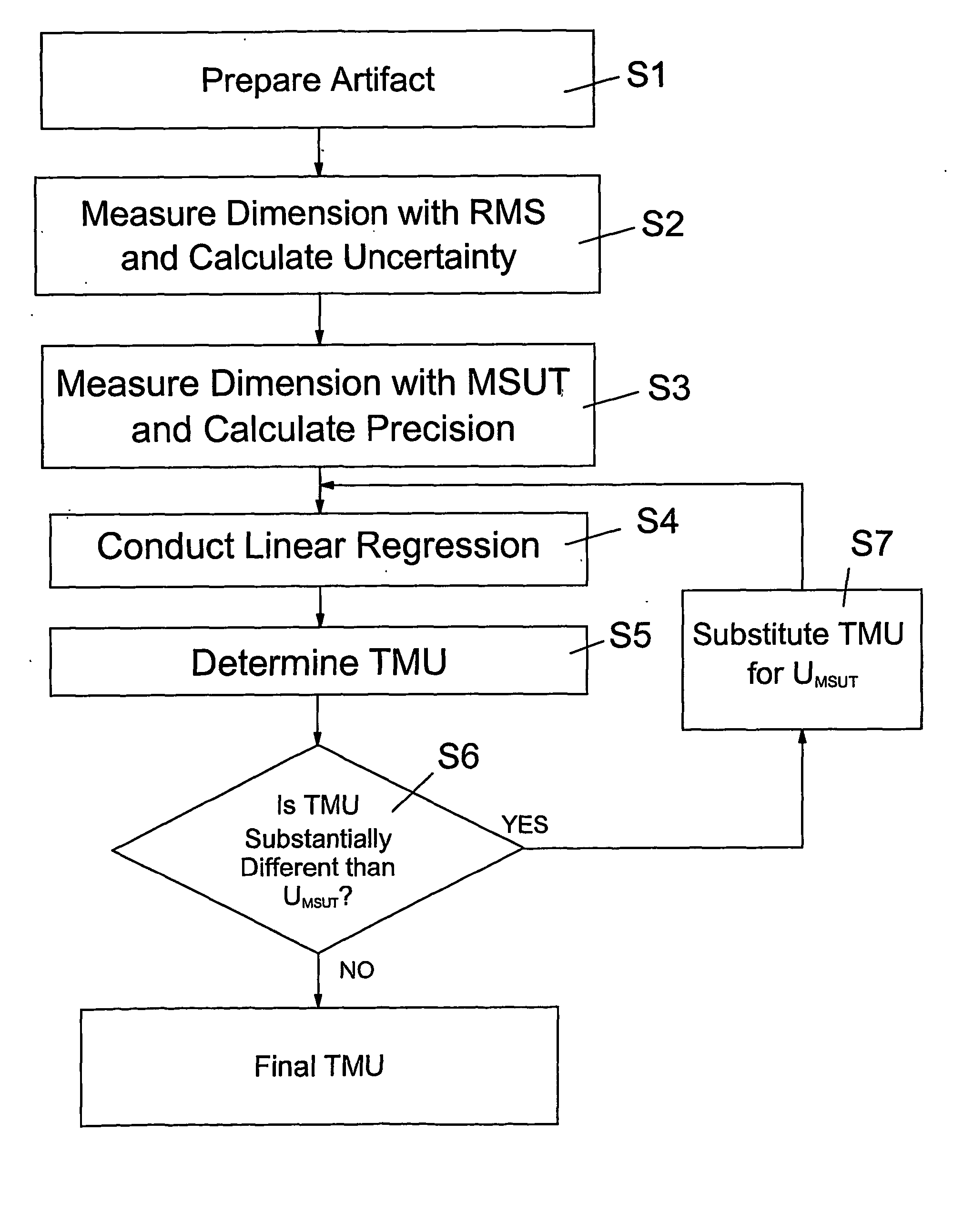
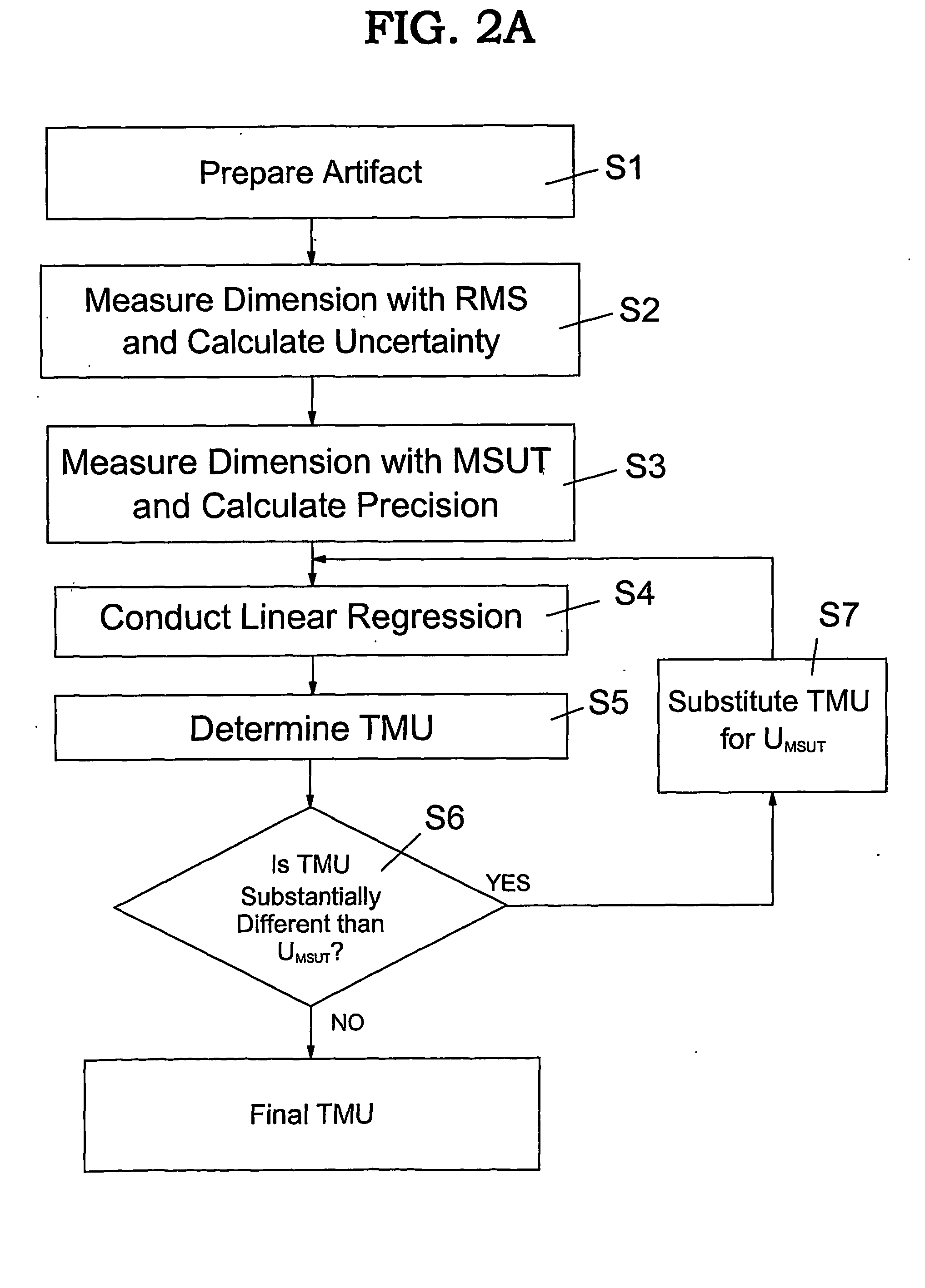
Methods and related program product for assessing and optimizing metrology instruments by determining a total measurement uncertainty (TMU) based on precision and accuracy. The TMU is calculated based on a linear regression analysis and removing a reference measuring system uncertainty (URMS) from a net residual error. The TMU provides an objective and more accurate representation of whether a measurement system under test has an ability to sense true product variation.

Description

TECHNICAL FIELD [0001] The present invention relates generally to metrology instruments. BACKGROUND ART [0002] Efficient semiconductor manufacturing requires highly precise and accurate metrology instruments. In particular, a metrology instrument is required to achieve small tolerances to achieve better quality products and fewer rejections in the manufacturing process. For example, the 1999 Edition of the International Technology Roadmap for Semiconductors lists the necessary precision needed for isolated line control in the year 2001 to be 1.8 nm. Unfortunately, correctly assessing and optimizing the measurement potential of a metrology instrument is difficult for a number of reasons. For example, an evaluator normally has limited access to the various instruments under consideration. In addition, each instrument needs to be evaluated under a wide range of conditions in order to gain a valid impression of how it will perform in the actual manufacturing setting. Finally, there are ...

Claims


Application Information

Patent Timeline
Patent Type & Authority Applications(United States)
IPC IPC(8): G03F7/20G06F15/00G06F19/00
CPCG01B21/045H01L22/12G03F7/70616G03F7/70483
Inventor ARCHIE, CHARLES N.BANKE JR, G. WILLIAM
Owner INT BUSINESS MASCH CORP
Why Eureka
Try Eureka