Two speed electric motor with link wound dual-commutator and dual-armature winding

a dual-commutator, armature technology, applied in the direction of dynamo-electric components, magnetic circuit rotating parts, magnetic circuit shape/form/construction, etc., can solve the problems of product market share loss and additional energy loss

Inactive Publication Date: 2005-10-13
BROSE FAHRZEUGTEILE GMBH & CO KG HALLSTADT (DE)
View PDF17 Cites 12 Cited by
  • Summary
  • Abstract
  • Description
  • Claims
  • Application Information

AI Technical Summary

Benefits of technology

[0009] An object of the invention is to fulfill the need referred to above. In accordance with the principles of the present invention, this objective is achieved by providing a permanent magnet D.C. electric motor including a stator housing; permanent magnet structure carried by the stator housing for creating a fixed magnetic flux field therein; an armature assembly installed in the stator housing, the armature assembly including a shaft rotatably mounted in the stator housing, lamination structure, first and second coil windings associated with the lamination structure, a first commutator electrically connected with the first coil winding, and a second commutator electrically connected with the second coil winding, each of the first and second commutators being generally cylindrical and having a plurality of commutator segments, commutator segments of the first commutator that are disposed 720 / N degrees apart being electrically connected and commutator segments of the second commutator that are disposed 720 / N degrees apart being electrically connected, wherein N is the number of magnetic poles of the motor and is an integer greater than 2. The motor includes a brush card assembly with a high speed side having first brush structure operatively associated with the first commutator, and a low speed side opposite the high speed side. The low speed side has a second brush structure operatively associated with the second commutator. Due to electrically connecting commutator segments, fewer brushes are required to operate the motor at at least two different speeds.

Problems solved by technology

Compared to series resistor solution / method for low speed, beside the conventional motor losses, there is an additional loss of energy.
The conventional motor shown in FIG. 1 was a high selling product in engine cooling for automotive applications, but with the development of more cost effective and reliable resistors, this product lost market share.

Method used


Image

  • Two speed electric motor with link wound dual-commutator and dual-armature winding
  • Two speed electric motor with link wound dual-commutator and dual-armature winding
  • Two speed electric motor with link wound dual-commutator and dual-armature winding

Examples


Embodiment Construction

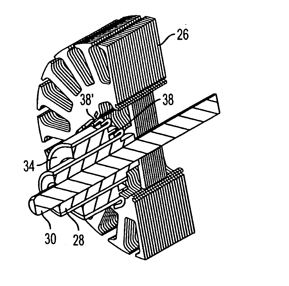
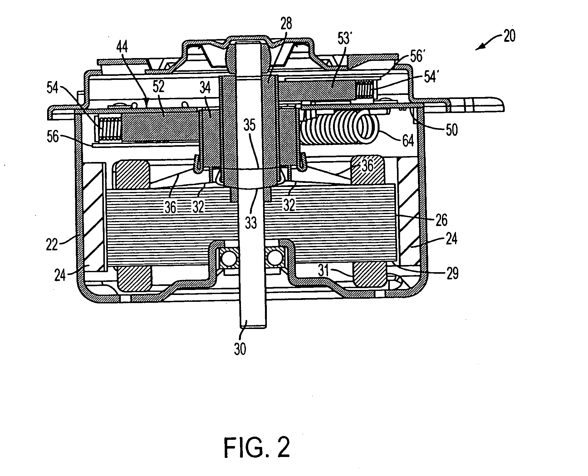
[0022] With reference to FIG. 2, a permanent magnet DC brush motor of link wound, dual commutator and dual winding configuration is shown, generally indicated at 20, in accordance with the principles of the present invention. The motor 20 includes a stator housing 22 carrying permanent magnets 24 for creating a fixed magnetic flux field therein. An armature assembly is installed in the stator housing 22. The armature assembly includes a shaft 30 rotatably mounted in the stator housing, lamination structure or stack 26 having a plurality of radially extending arms 27 defining a plurality of coil receiving peripheral slots 29 there-between (FIG. 3a), first and second coil windings in the slots (winding mass is shown in FIG. 1 at 31), a link wound, low speed (LS) commutator electrically connected with a LS winding 32 and coupled with the shaft 30, and a link wound high speed HS commutator 34 electrically connected with an HS coil winding 36 mounted over the LS commutator 28. A link win...


PUM


Abstract

A permanent magnet D.C. electric motor includes a stator housing, permanent magnet structure, and an armature assembly. The armature assembly includes a shaft rotatably mounted in the stator housing, lamination structure, first and second coil windings associated with the lamination structure, a first commutator electrically connected with the first coil windings, and second commutator electrically connected with the second coil windings, each of the first and second commutators being generally cylindrical and having a plurality of commutator segments. Certain segments of the first commutator and certain segments of the second commutator are electrically connected. The motor also includes a brush card assembly including a high speed side having first brush structure associated with the first commutator, and a low speed side having a second brush structure associated with the second commutator, and switches for selectively connecting a D.C. voltage in such a way as to cause the armature assembly to rotate at a first speed and a second speed.

Description

[0001] This application is based on U.S. Provisional No. 60 / 560,457 filed on Apr. 8, 2004 and No. 60 / 579,949, filed on Jun. 15, 2004 and claims the benefit thereof for priority purposes.FIELD OF THE INVENTION [0002] This invention relates to automotive applications such as engine cooling, HVAC (Heating, Ventilation and Air Conditioning), or ABS (Anti-lock Braking System) and, more particularly, to an electric motor with link wound dual commutator and dual armature winding. BACKGROUND OF THE INVENTION [0003] Often permanent magnet motors used in automotive application require the use of more than one speed, usually a lower speed for general purpose operation and a maximum speed for worst-case operation. Multiple speed operation of a cooling system module of a vehicle provides a more optimized engine temperature and operation, which consequently contributes to improved fuel economy. [0004] For permanent magnet direct current brush motors (PMDCBM), historically lower speeds (multiple s...

Claims


Application Information

Patent Timeline
Patent Type & Authority Applications(United States)
IPC IPC(8): H02K13/00H02K23/36H02K27/24
CPCH02K23/36
Inventor SIMOFI-ILYERS, ATTILALAKERDAS, ANDREWVOLKENING, MARTINSMOROWSKI, STEFAN
Owner BROSE FAHRZEUGTEILE GMBH & CO KG HALLSTADT (DE)
Why Eureka
Try Eureka