
Method for manufacturing piezoelectric film, laminate structure of substrate and piezoelectric film, piezoelectric actuator, and method for manufacturing same

a piezoelectric film and substrate technology, applied in piezoelectric/electrostrictive/magnetostrictive devices, printing, generators/motors, etc., can solve the problems of difficult film formation conditions, poor piezoelectric characteristics, and deterioration of film so as to reduce adhesion and dielectric strength characteristics, the effect of high electrical and chemical activity

Inactive Publication Date: 2005-10-13
NAT INST OF ADVANCED IND SCI AMD TECH
View PDF14 Cites 6 Cited by
  • Summary
  • Abstract
  • Description
  • Claims
  • Application Information

AI Technical Summary

Benefits of technology

[0006] The present invention was made in view of the above-mentioned situation, and it is an object thereof to provide a simple method for manufacturing a piezoelectric film that will simultaneously satisfy the various characteristics required thereof.
[0028] With the present invention, a piezoelectric film having a layer with good adhesion on the side facing the substrate, and having a layer with good piezoelectric characteristics on the outside can be produced, and both good adhesion to the substrate and good piezoelectric characteristics can be achieved. Also, since layers having different properties can be laminated by the same AD method merely by varying the film formation conditions, it is possible to obtain a piezoelectric film having good characteristics without a complicated manufacturing process.

Problems solved by technology

For instance, if the ejection velocity of the aerosol onto the substrate is raised, the adhesion of the film to the substrate and the dielectric strength characteristics of the film improve, but the piezoelectric characteristics of the film tend to deteriorate.
Furthermore, satisfactory piezoelectric characteristics are not always obtained even if annealing is performed (a treatment in which the film is heated for improving its piezoelectric characteristics).
Thus, it was difficult to find film formation conditions under which the various characteristics required of a piezoelectric film would simultaneously be satisfied.
In this case, it is quite conceivable that the grain boundary planes of these particles that have taken on a fine structure will be complex, so it is surmised that there is an increase in the grain boundary distance in the thickness direction of the piezoelectric film.

Method used


Image

  • Method for manufacturing piezoelectric film, laminate structure of substrate and piezoelectric film, piezoelectric actuator, and method for manufacturing same
  • Method for manufacturing piezoelectric film, laminate structure of substrate and piezoelectric film, piezoelectric actuator, and method for manufacturing same
  • Method for manufacturing piezoelectric film, laminate structure of substrate and piezoelectric film, piezoelectric actuator, and method for manufacturing same

Examples


example 1

1) Film Formation

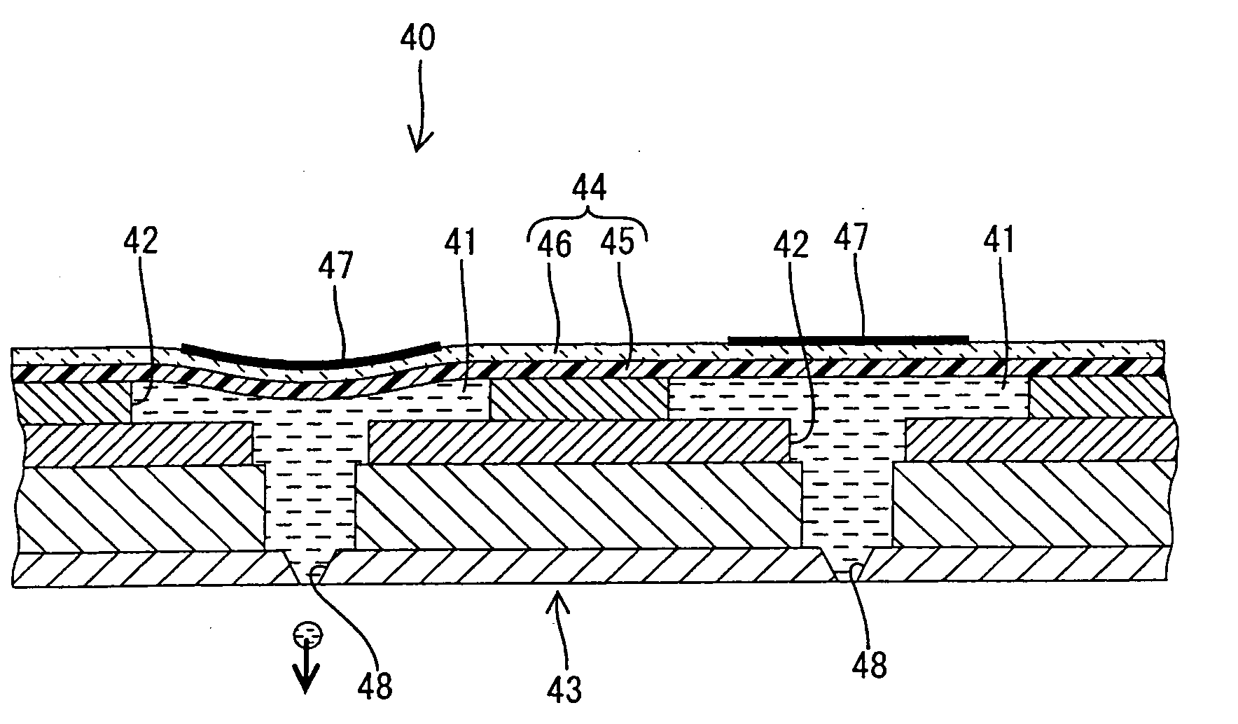
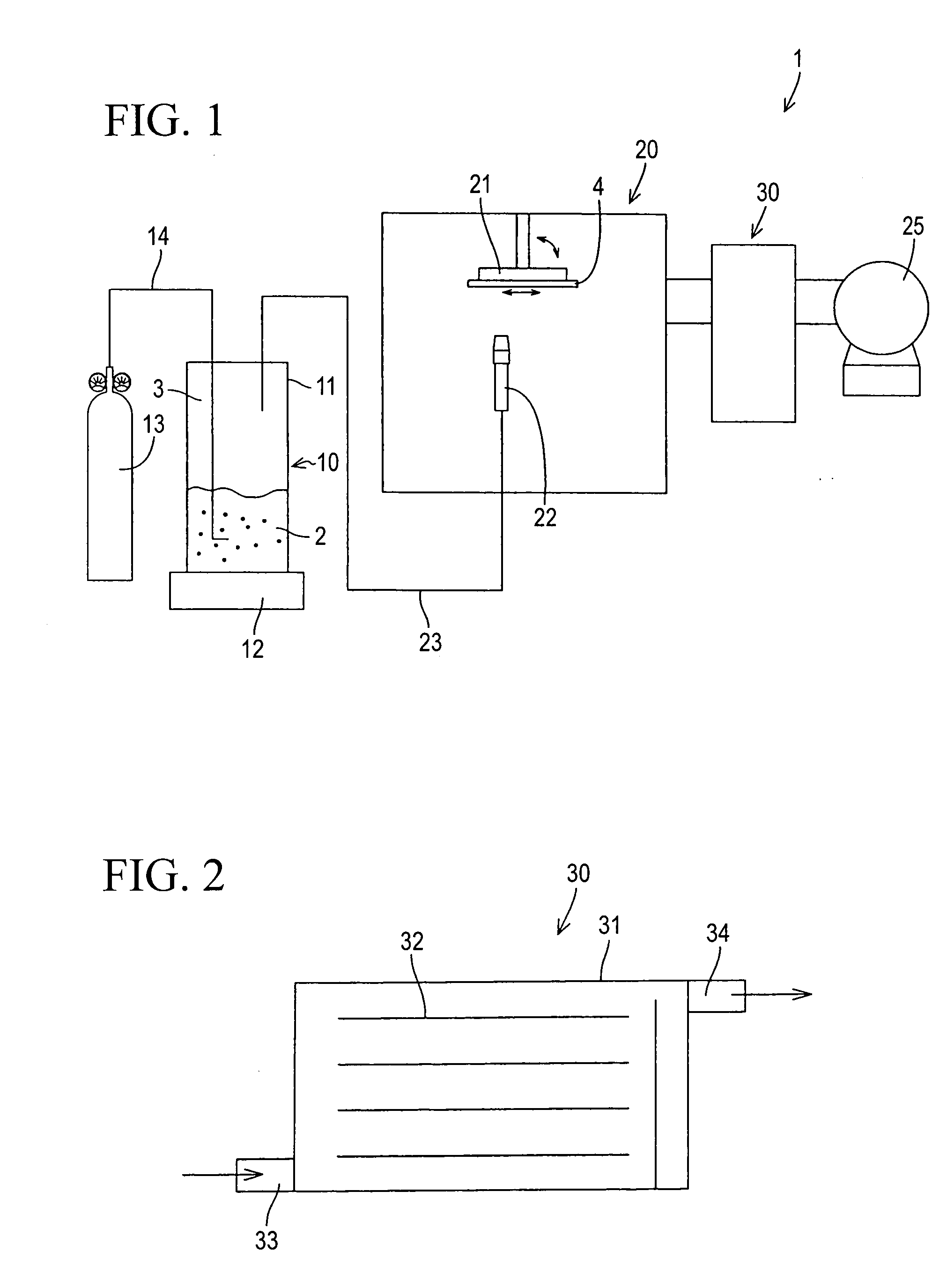
[0058] A sheet of ferritic stainless steel (SUS430 prescribed by Japanese Industrial Standards) with a Vickers hardness Hv of 300 was used as a substrate. PZT with a Vickers hardness Hv of 300 to 400 and an average particle size of 0.3 to 1 μm was used as the material particles. A piezoelectric film was formed on the substrate with the sample film formation apparatus as in the embodiment described above. The Vickers hardness of the substrate and the particles was measured with a Nano-Hardness Tester made by +CSM Instruments.

[0059] Here, a first piezoelectric layer was formed on the substrate by ejecting the particles of PZT at a particle velocity of 400 m / sec (first film formation step), and then a second piezoelectric layer was formed on this first piezoelectric layer by ejecting the same at a particle velocity of 170 m / sec (second film formation step). After this, annealing was performed for 1 hour at 600° C. to form a piezoelectric film with a thickness of 10 ...

example 2

[0064] Piezoelectric films were formed in a single film formation step by varying the particle velocity between 150 and 450 m / sec. The rest of the film formation conditions were the same as in Example 1. The piezoelectric films thus obtained were tested in the same manner as in Example 1.

Results and Discussion

1. Comparison of Two-Layer Piezoelectric Film and Single-Layer Piezoelectric Film

1) Adhesion

[0065] Adhesion was measured by tensile test with a tensile tester. More specifically, in this test, a jig with a cross sectional area of 25 mm2 was bonded with an epoxy-based adhesive to the surface of the film that had been formed, and this jig was then pulled off.

[0066] The piezoelectric films adhered tightly to the substrate both when two layers of piezoelectric film were formed at a particle velocity of 400 m / sec and 170 m / sec (Example 1) and when one layer of piezoelectric film was formed at a particle velocity of 400 m / sec (Comparative Example 1). The piezoelectric films h...


PUM

PropertyMeasurementUnit
aerosol ejection velocityaaaaaaaaaa

Abstract

The present invention provides a simple method using aerosol deposition, for manufacturing a piezoelectric film that will simultaneously satisfy various characteristics required of a piezoelectric film. In the method, the piezoelectric film is formed on a substrate by ejecting an aerosol containing particles of a piezoelectric material onto the substrate so that the particles adhere thereto, and a second piezoelectric layer is formed on the first piezoelectric layer by conducting the ejection such that energy used for crushing the particles when the particles collide with the substrate is less than in the formation of the first piezoelectric film.

Description

BACKGROUND OF THE INVENTION [0001] 1. Field of the Invention [0002] The present invention relates to a method for manufacturing a piezoelectric film, to a laminate structure of a substrate and a piezoelectric film, to a piezoelectric actuator, and to a method for manufacturing the same. [0003] 2. Description of the Related Art [0004] A method called aerosol deposition (AD) is one way to manufacture piezoelectric actuators and the like used in the printer heads of inject printers and so on. This method involves dispersing microparticles of a piezoelectric material in gas to produce an aerosol, and ejecting this aerosol toward a substrate surface, and causing the microparticles to collide with and be deposited on the substrate to form a piezoelectric film (see Japanese Patent Application Laid-Open No. 2001-152360 and Japanese Patent Application Laid-Open No. H11-330577, for example). SUMMARY OF THE INVENTION [0005] According to the research conducted by the inventors, there has been f...

Claims


Application Information

Patent Timeline
Patent Type & Authority Applications(United States)
IPC IPC(8): B41J2/16B41J2/14C23C24/04H01L41/09H01L41/187H01L41/22H01L41/314H01L41/43
CPCC23C24/04H01L41/081H01L41/0973H01L41/1876H01L41/314Y10T29/42Y10T29/49401H10N30/2047H10N30/8554H10N30/074H10N30/706
Inventor YASUI, MOTOHIROAKEDO, JUN
Owner NAT INST OF ADVANCED IND SCI AMD TECH
Learn More