Node-to node messaging transceiver network with dynamec routing and configuring

a messaging transceiver and routing technology, applied in the field of multi-level networks, can solve the problems of complex networks, inability to cost justify many more potential applications using this technology, and high equipment and airtime costs of real-time connections

Inactive Publication Date: 2005-10-13
AFX TECH GRP INT
View PDF64 Cites 379 Cited by
  • Summary
  • Abstract
  • Description
  • Claims
  • Application Information

AI Technical Summary

Benefits of technology

[0006] It is an object of this invention to provide a low cost, multi-node system which hands off messages from node-to-node; a system of nodes which hands off messages and provides implicit and / or explicit acknowledgment of the hand off; a flexible, adaptable multi-node system which is applicable in a plurality of environments and for a plurality of uses; a multi-node system having stationary nodes and mobile nodes (known as “Minion™ devices”) the position of which can be determined by the stationary nodes; a multi-node system which permits nodes to communicate with a wide area network or a global positioning system via a selected number of nodes; a multi-node system which operates multiple applications at each node; and a multi-node system which interfaces with a plurality of “gateways”, e.g., wide area network (WAN) connections to other communications networks, whether wired or not, such as telephone or CATV or wireless, or satellite or terrestrial.

Problems solved by technology

Such networks are complex and are based on the apparent need for real time connectivity.
Real-time connections are very expensive in terms of equipment and air-time.
Many wireless data applications have been designed around real-time communications because it has been available, but many more potential applications have been unable to be cost justified using this technology.
For many applications the requirement for a real-time connection is an artificial constraint, and has limited the development of short-range messaging between devices.
Even though there may be thousands of actual phones in the area, they are not capable of direct communication with each other.

Method used


Image

  • Node-to node messaging transceiver network with dynamec routing and configuring
  • Node-to node messaging transceiver network with dynamec routing and configuring
  • Node-to node messaging transceiver network with dynamec routing and configuring

Examples


Embodiment Construction

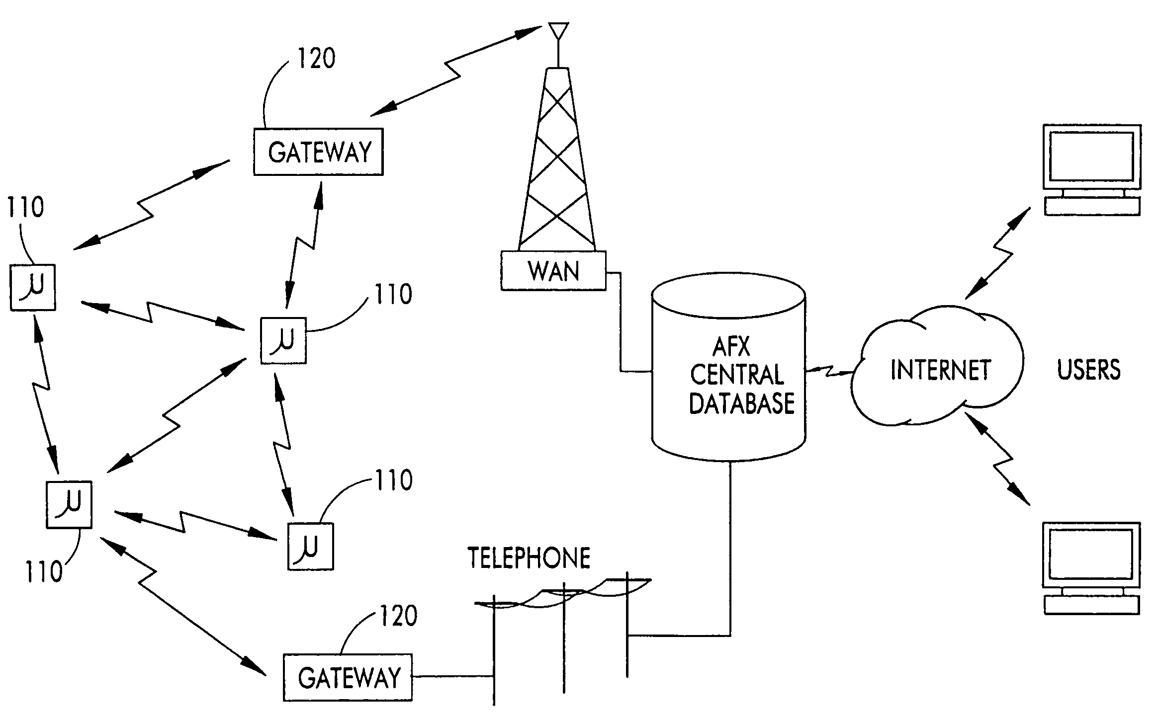
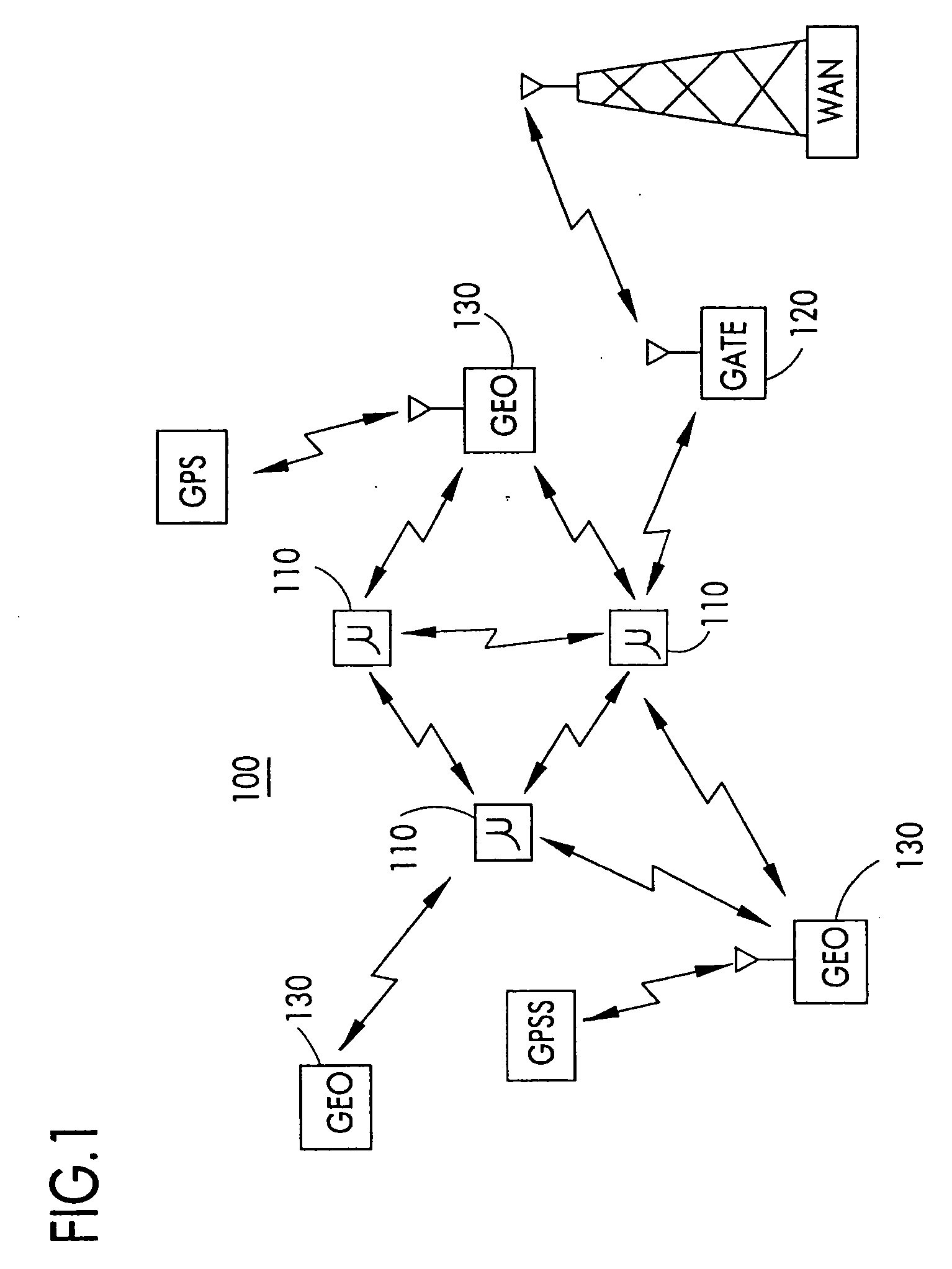
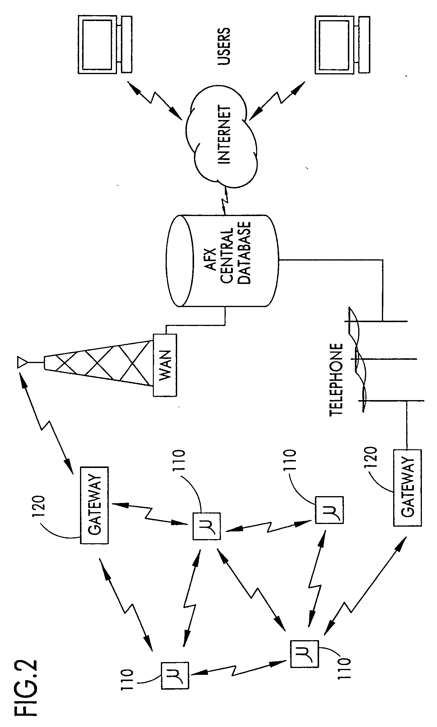
[0040] The MinionNet™ Network 100 as illustrated in FIGS. 1 and 2 is a wireless data network characterized by short-range device-to-device messaging. (Minion™, MinionNet™, μMinion™, muMinion™, microMinion™, gatewayMinion™, geoMinion™ and cap™ are trademarks of the assignee. As used hereinafter, Minion device means Minion™, MinionNet™, μMinion™, muMinion™, microMinion™, gatewayMinion™, and / or geoMinion™, unless otherwise specified. The trademark designation “™” will not be used hereafter for convenience.) Messages are automatically routed through multiple device-to-device “hops” to provide robust area coverage, redundancy, noise immunity and dynamic routing and reconfiguration. These device-to-device messages do not have a time-critical requirement such as would be found in a real-time voice connection such as a cellular telephone net.

[0041] The devices used by the MinionNet network 100 are generally referred to as Minion devices and are actually extremely inexpensive two-way data r...


PUM


Abstract

The invention is a system operating on a reference frequency. The system comprises a plurality of at least three nodes. Each node hands off a message received from another node to a subsequent node. Each of the nodes comprises a transceiver receiving a message on the reference frequency from another node and transmitting the received message on the reference frequency to a subsequent node, and a controller controlling operation of the transceiver to receive the message transmitted by another node and to transmit the received message to a subsequent node.

Description

BACKGROUND OF THE INVENTION [0001] 1. Field of the Invention [0002] The invention generally relates to multilevel networks and, in particular, to a wireless network of intelligent transceiver nodes which employ local processing and node-to-node data messaging to hand off messages from an origination point to a destination point. [0003] 2. Description of the Prior Art [0004] Wireless networks such as the cellular phone system are well known in the prior art. Such networks are complex and are based on the apparent need for real time connectivity. Consumer applications of networks such as cellular phones have promoted a perception that robust real-time connections are a requirement of wireless communications. Real-time connections are very expensive in terms of equipment and air-time. Many wireless data applications have been designed around real-time communications because it has been available, but many more potential applications have been unable to be cost justified using this tech...

Claims


Application Information

Patent Timeline
Patent Type & Authority Applications(United States)
IPC IPC(8): H04L12/28H04L12/56H04L12/58H04W40/06H04W40/10H04W40/20H04W40/24H04W40/30H04W88/04
CPCH04L12/5895H04L45/00H04W40/06H04W88/04H04W40/20H04W40/248H04W40/30H04W40/10Y02D30/70H04L51/58
Inventor MCMILLIN, BRIAN K.
Owner AFX TECH GRP INT
Why Eureka
Try Eureka