Supercharge Your Innovation With Domain-Expert AI Agents!

Heating device and image forming apparatus

a technology of image forming apparatus and heating device, which is applied in the direction of electric/magnetic/electromagnetic heating, electrographic process, instruments, etc., can solve the problems of insufficient mechanical strength, long waiting time (the time from the main switch actuation to the printable state reached), and large electric power consumption to raise the temperature of the fixing nip. , to achieve the effect of saving space, low cost and saving electric power

Inactive Publication Date: 2005-10-13
CANON KK
View PDF11 Cites 3 Cited by
  • Summary
  • Abstract
  • Description
  • Claims
  • Application Information

AI Technical Summary

Benefits of technology

This solution effectively prevents undesirable temperature changes, enhances space efficiency, reduces power usage, and improves throughput by dynamically adjusting heat generation based on the size of the recording material, ensuring consistent and efficient image fixing without compromising speed.

Problems solved by technology

However, the fixing roller has a large thermal capacity, and the electric power required for heating through roller is large, with the result that waiting time (the time from the main switch actuation to the printable state reached) is long.
However, doing so results in an insufficient mechanical strength.
However, since the thermal capacity of the fixing roller is large, the electric power consumption to raise the temperature of the fixing nip is still large.
However, in the film-like fixing roller, the heat flow is not good in the longitudinal direction of the fixing nip, with the result that when a small size recording material is passed through the nip, a problem of excessive temperature rise arises, the problem decreases the lifetime of the film and / or the pressing roller.
The problem of the temperature rise at the non-sheet-passage-part also arises in the apparatus of the film heating type described in b.
However, a shield plate for shielding the magnetic flux toward the fixing roller or the film from the coil and a mechanism for moving the shield plate are bulky.
This method result in decreased throughput.
However, the throughput of the image forming apparatus decreases.

Method used


Image

  • Heating device and image forming apparatus
  • Heating device and image forming apparatus
  • Heating device and image forming apparatus

Examples


embodiment 1

(Embodiment 1)

(1) Example of Image Forming Apparatus

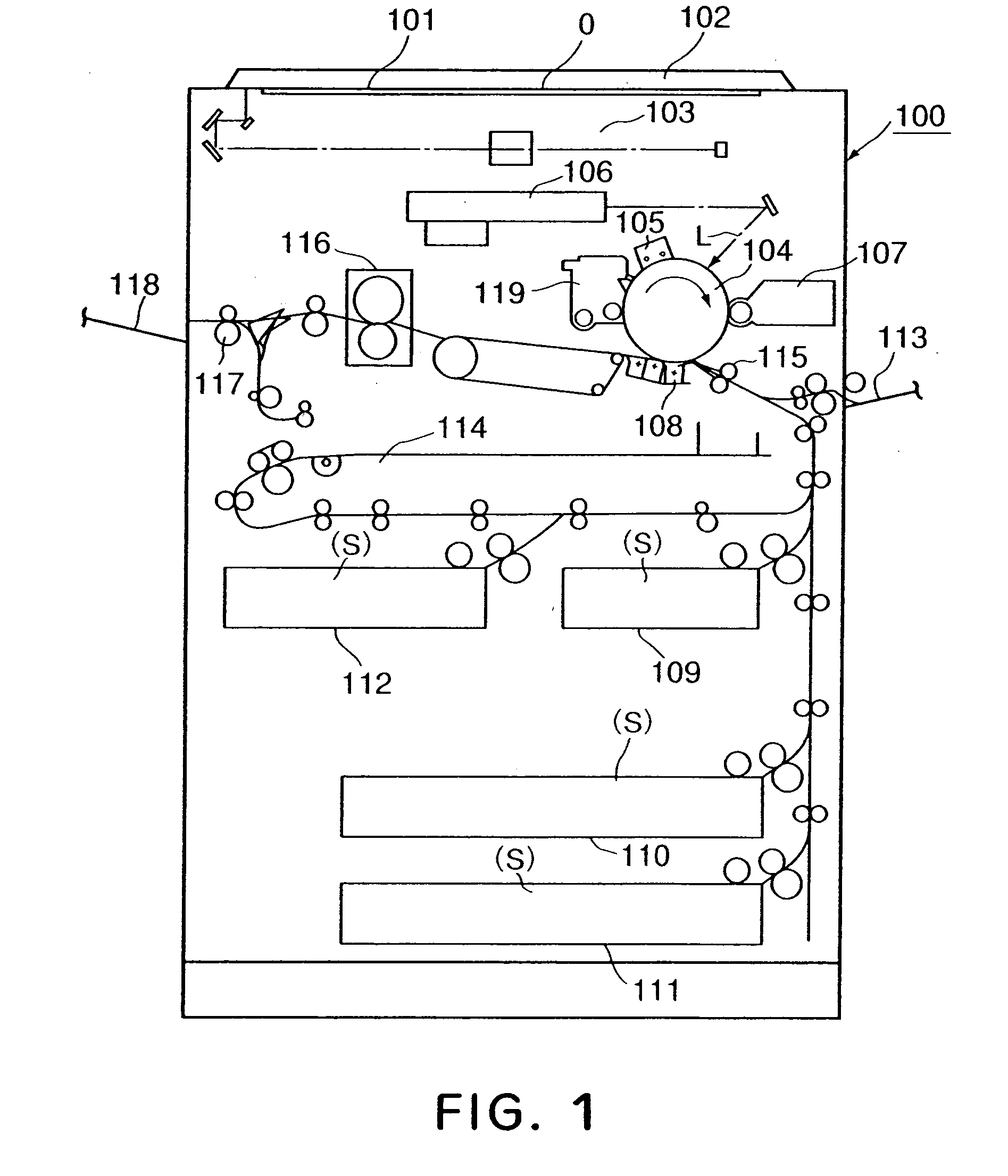
[0035]FIG. 1FIG. 1 is a schematic general arrangement of an image forming apparatus 100 according to a first embodiment of the present invention. In this embodiment, the image forming apparatus 100 is a laser copying machine using an image transfer type electrophotographic process.

[0036] Designated by 101 is an original supporting platen glass, on which an original O is placed face down at a predetermined position, and is covered by an original cover 102. When a copy start key is depressed, an image photoelectric reading apparatus including a movement optical system (reader) 103 is operated, so that image information of the original O on the original supporting platen glass 101 is photo-electrically read. On the original supporting platen glass 101, an original automatic feeding apparatus (ADF, RDF) may be provided such that originals are automatically fed onto the original supporting platen glass 101.

[0037] Designated by 104 i...

embodiment 2

(Embodiment 2)

[0087]FIG. 8-s 12 illustrates a second embodiment. The same reference numerals as with the first embodiment are assigned to the elements having the corresponding functions.

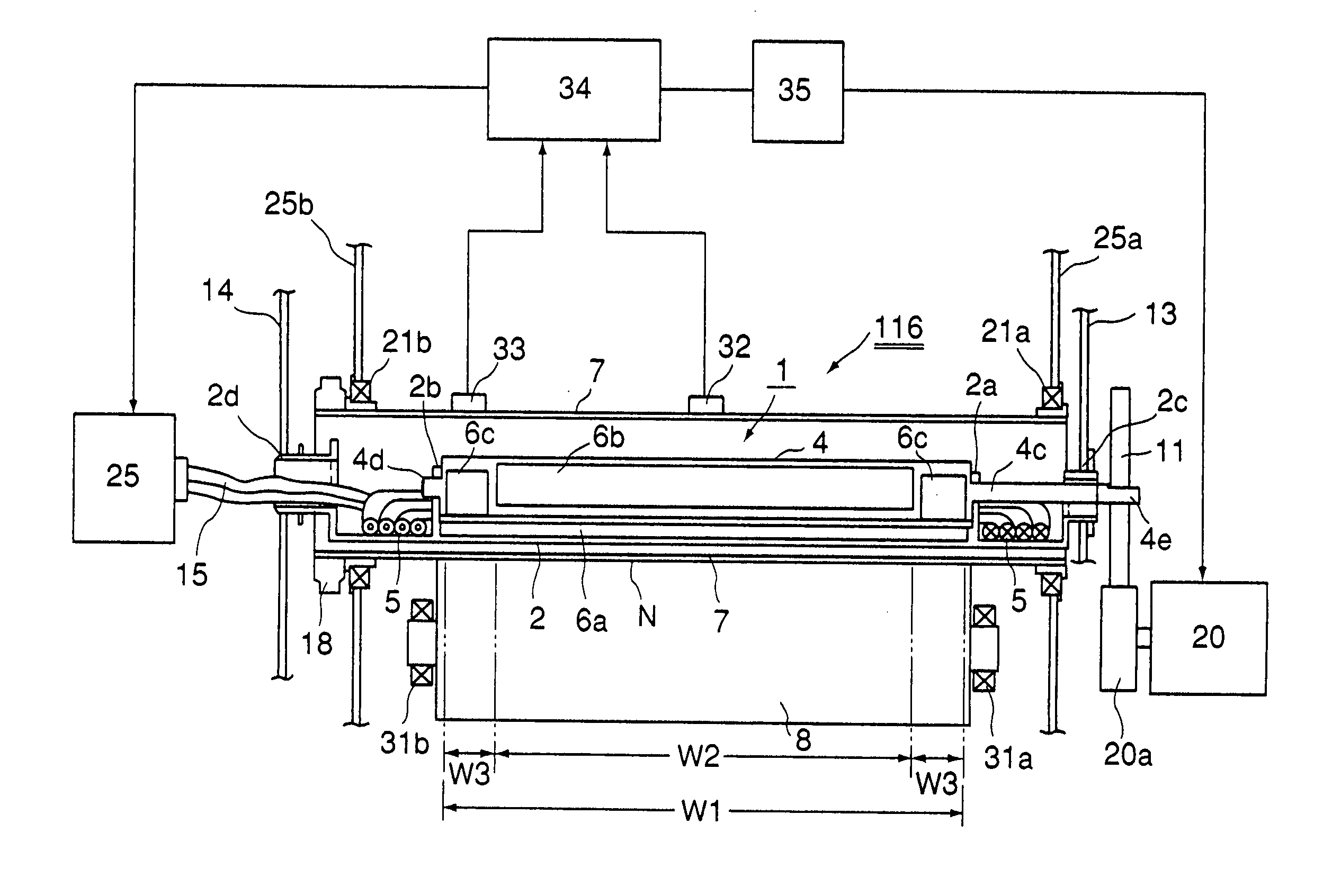
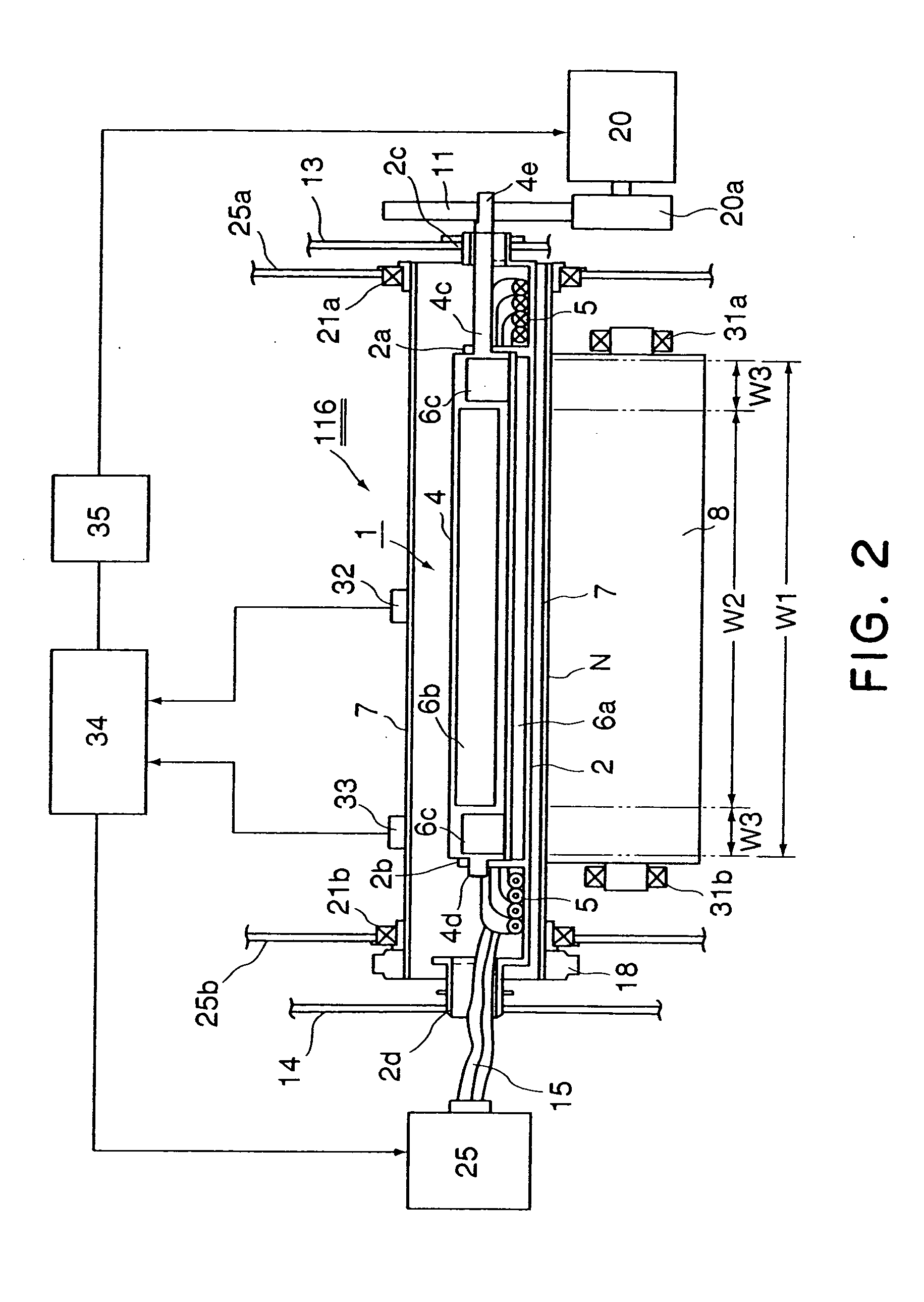
[0088] In this embodiment, the function of the second core 6b in the first embodiment is assigned to the first core 6a, by which the second core supported by the rotatable core supporting member 4 is provided only at the opposite end portions (cores 6c and 6c).

[0089] The space occupied by the core of the magnetic flux generating means is small, and from the standpoint of the heat generating efficiency, this embodiment is inferior to the first embodiment, but the core member is simplified, and the cost can be reduced. [0090] (1) FIG. 8 deals with the case in which the recording material S (A4) having the normal paper size width W1 with which the undesirable temperature rise does not occur at the non-sheet-passage-part, is used, and the rotatable core supporting member 4 takes the first angular posit...


PUM


Abstract

A heating apparatus has an excitation coil; magnetic flux generator having a magnetic member core, the magnetic member core having a first magnetic core supported with a holder for the excitation coil and a rotatable second magnetic member core; an induction heat generating element for electromagnetic induction heat generation using the magnetic flux generated by the magnetic flux generator; a heating portion for receiving a recording material and for heating the recording material by the heat generated by the induction heat generating element; and a rotator for rotating second magnetic core to a different angular position to change a heat generation distribution in a longitudinal direction of the induction heat generating element.

Description

FIELD OF THE INVENTION AND RELATED ART [0001] The present invention relates to a heating apparatus of an electromagnetic (magnetic) induction heating type and an image forming apparatus comprising the same as an image heating means for image fixing or the like. [0002] An image heat-fixing device in an image forming apparatus such as an electrophotographic copying machine, printer or facsimile machine will be taken as an example. [0003] In the image forming apparatus, a toner (visualization material) of heat-fusing property resin material or the like is formed directly or indirectly (image transfer) on a recording material by image forming process means of an electrophotographic, electrostatic recording, magnetic flux recording type or the like in an image forming station of the image forming apparatus. The toner image thus formed is not yet fixed. It is fixed into a permanent fixed image by heat fixing process on the surface of the recording material. [0004] As for such an image hea...

Claims


Application Information

Patent Timeline
Patent Type & Authority Applications(United States)
IPC IPC(8): G03G15/20H05B6/14H05B6/40H05B6/44
CPCG03G15/2053G03G15/2042H05B6/145
Inventor SEKIGUCHI, HAJIMEFUSEYA, ATSUSHI
Owner CANON KK
Features
  • R&D
  • Intellectual Property
  • Life Sciences
  • Materials
  • Tech Scout
  • Unparalleled Data Quality
  • Higher Quality Content
  • 60% Fewer Hallucinations
Learn More