
Fuel cell system

Inactive Publication Date: 2005-10-13
HONDA MOTOR CO LTD
View PDF2 Cites 15 Cited by
  • Summary
  • Abstract
  • Description
  • Claims
  • Application Information

AI Technical Summary

Benefits of technology

[0012] In accordance with the first aspect of the fuel cell system, the upper limit value of the power generation current can be set without using a refrigerant temperature detection mechanism such as a water temperature sensor. In addition, in accordance with the second aspect of the fuel cell system, even if the refrigerant temperature detection mechanism and the like malfunction, an operation is enabled in a range of heat damage and the like not occurring in the fuel cell.

Problems solved by technology

In this connection, the fuel cell becomes highest in its power generation performance (electromotive force) by a temperature thereof being maintained at a predetermined value (for example, 80 degrees Celsius): if the temperature is too low, the power generation performance lowers; and if too high, there occurs a possibility that a fuel cell main body and instruments (piping, valve, and the like) receive heat damage.
However, in the apparatus of the patent document 1, when there occur a malfunction of a water temperature sensor, a disconnection of an electric harness connected to the water temperature sensor, and the like, compensation control based on a cooling fluid temperature results in being not correctly performed and there is a possibility that following problems occur: For example, if the controller recognizes the cooling fluid temperature lower than actual one, an output (power generation current) results in being not limited in spite of the fuel cell temperature being high, and it may happen that an excessive temperature rise occurs in the fuel cell.
In addition, if the controller recognizes the cooling fluid temperature higher than actual one, the output is reduced in spite of the fuel cell temperature being an adequate value, and it may happen that the output is gradually reduced and the FCEV results in being unable to run.

Method used


Image

  • Fuel cell system
  • Fuel cell system
  • Fuel cell system

Examples


Embodiment Construction

[0017] Here will be described an embodiment in detail where the present invention is applied to a fuel cell electric automobile, referring to drawings as needed.

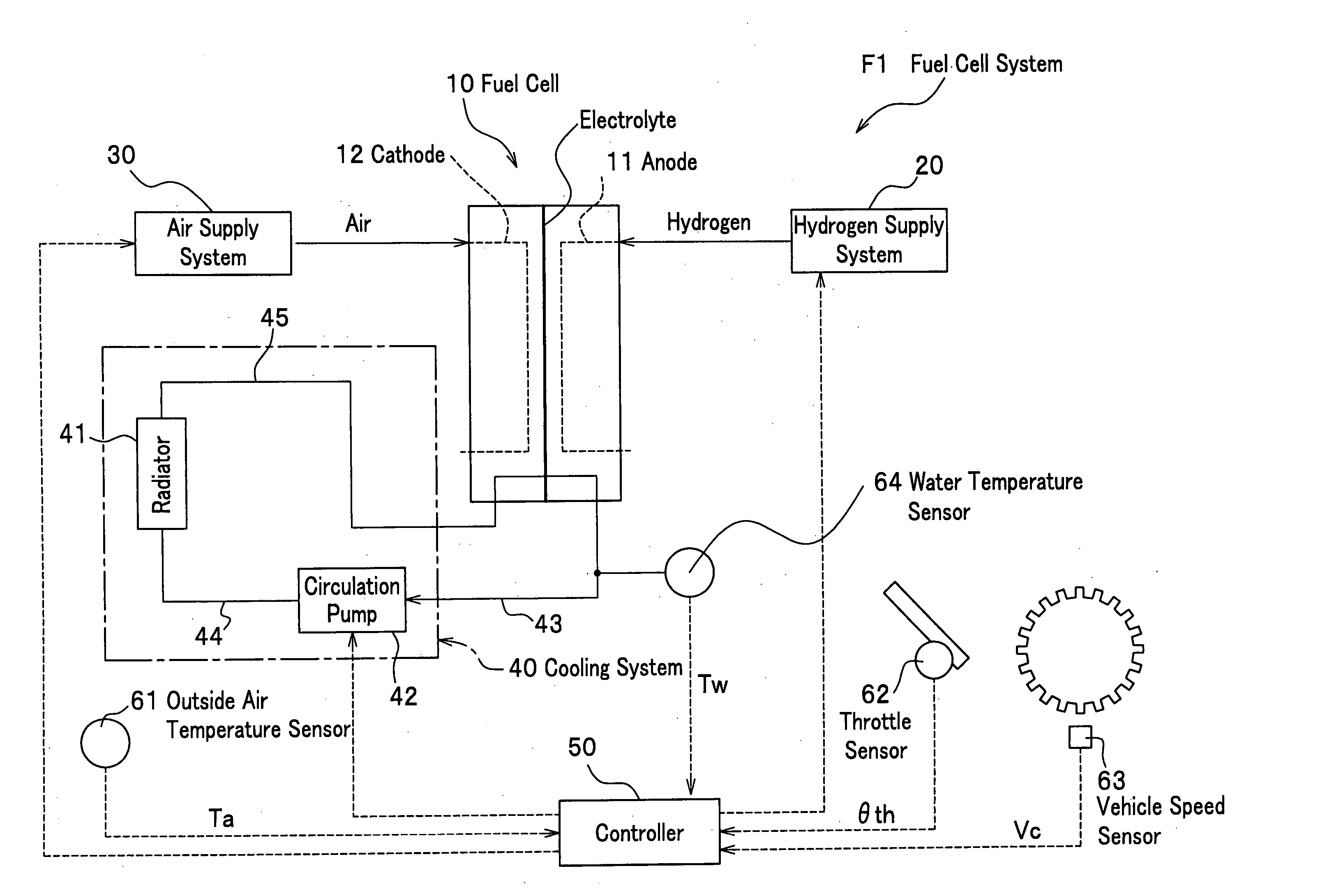
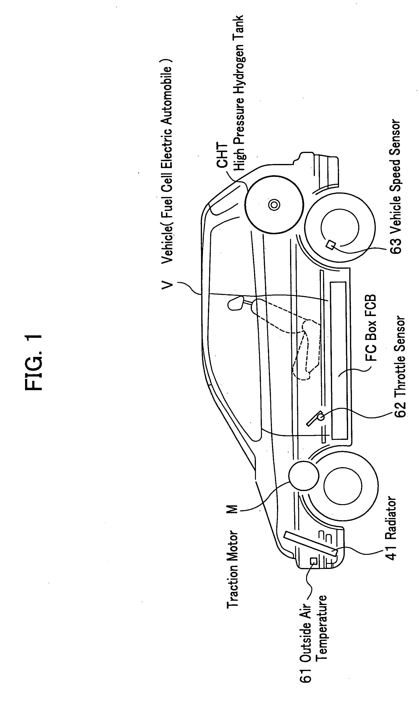
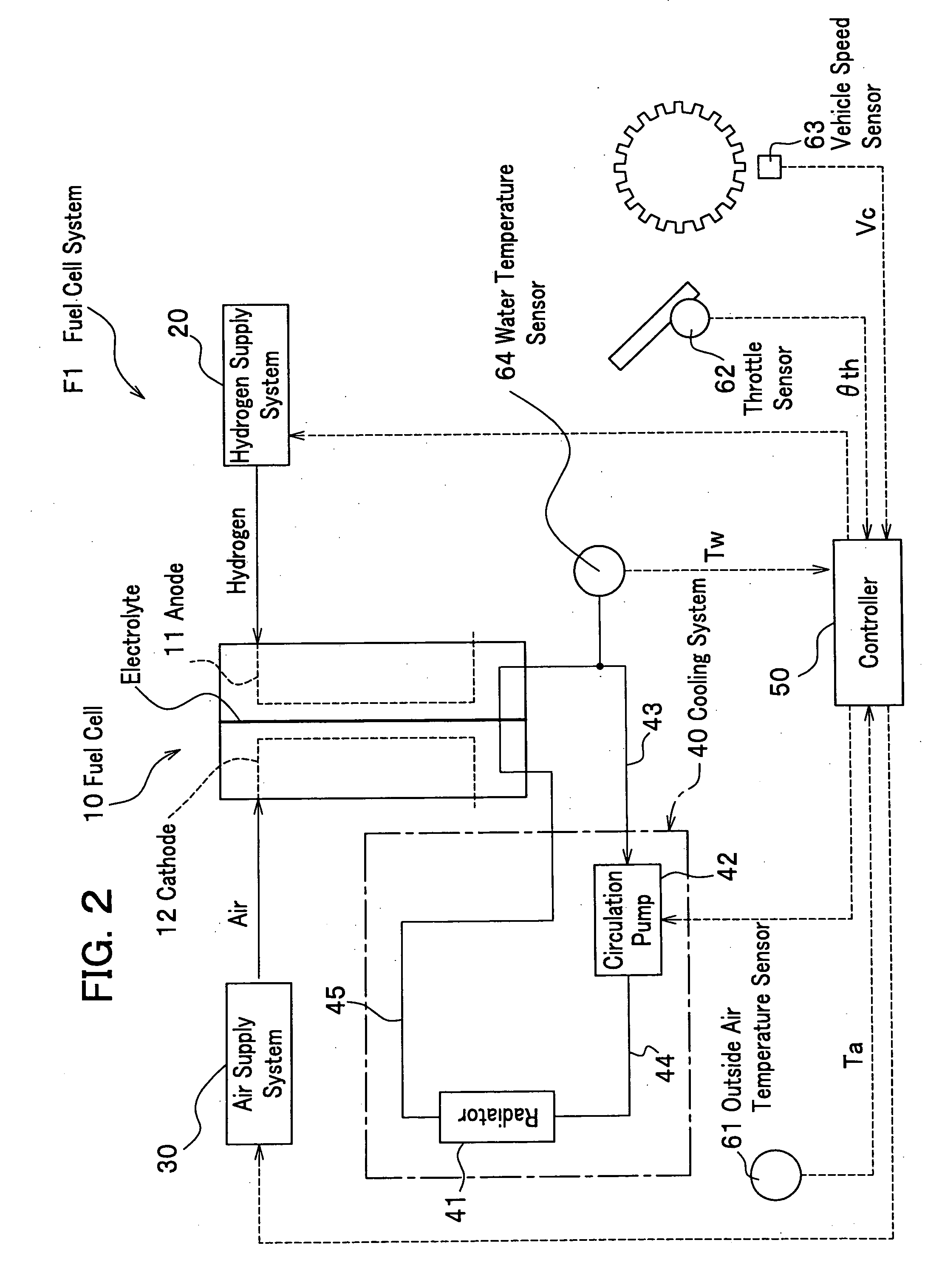
[0018]FIG. 1 is a partial perspective side view of a vehicle where a fuel cell system related to an embodiment of the present invention is mounted; FIG. 2 is a schematic configuration diagram of the fuel cell system related to the embodiment of the present invention.

[Vehicle Configuration]

[0019] Firstly will be described a vehicle. In a vehicle V shown in FIG. 1, an FC box FCB is mounted under a floor of a passenger's seat and a fuel cell 10 is housed in the FC box FCB (see FIG. 2). In addition, a traction motor M is mounted on a front area and a high pressure hydrogen tank CHT is horizontally mounted above rear wheels of the vehicle V. In addition, the vehicle V comprises a radiator 41 for radiating heat in a fuel cell cooling loop at a vehicle body front area and an outside air temperature sensor (outside air temperatur...


PUM


Abstract

A fuel cell system of the present invention is mounted on a moving object and is equipped with a fuel cell for generating power by chemically reacting a fuel gas supplied to an anode and an oxidizer gas supplied to a cathode; a cooling mechanism for cooling the fuel cell by radiating heat of a refrigerant circulating in the fuel cell into an atmosphere; a speed detection mechanism for detecting a moving speed of the moving object; an outside air temperature detection mechanism for detecting an outside air temperature; a cooling amount estimation mechanism for estimating a cooling amount of the fuel cell by the cooling mechanism, based on the moving speed and the outside air temperature; and an upper limit value set mechanism for setting an upper limit value of a power generation current, based on an estimation result of the cooling amount estimation mechanism.

Description

BACKGROUND OF THE INVENTION [0001] 1. Field of the Invention [0002] The present invention relates to a fuel cell system for a moving object that enables an operation of a fuel cell in a range of overheat not occurring in the fuel cell, even when a temperature detection mechanism of a cooling system malfunctions. [0003] 2. Description of the Related Art [0004] These years from such a viewpoint of suppressing a discharge amount of carbon dioxide that causes global warming is noticed a fuel cell electric vehicle (FCEV). The FCEV mounts a fuel cell (FC) for generating power by electrochemically reacting hydrogen (H2) and oxygen (O2) in air, supplies the power generated by the fuel cell to a traction motor, and produces driving force. [0005] In this connection, the fuel cell becomes highest in its power generation performance (electromotive force) by a temperature thereof being maintained at a predetermined value (for example, 80 degrees Celsius): if the temperature is too low, the power...

Claims


Application Information

Patent Timeline
IPC IPC(8): B60L11/18H01M8/04H01M8/00
CPCB60L11/1881B60L11/1892B60L11/1894H01M8/04007H01M8/04029H01M8/0432Y02T90/32H01M8/04731H01M8/0494H01M2250/20Y02T90/34Y02E60/50H01M8/04358B60L58/30B60L58/33B60L58/34Y02T90/40
Inventor UEDA, KENICHIROMIYATA, KOICHIRO
Owner HONDA MOTOR CO LTD
Features
  • Generate Ideas
  • Intellectual Property
  • Life Sciences
  • Materials
  • Tech Scout
  • Unparalleled Data Quality
  • Higher Quality Content
  • 60% Fewer Hallucinations
Learn More