

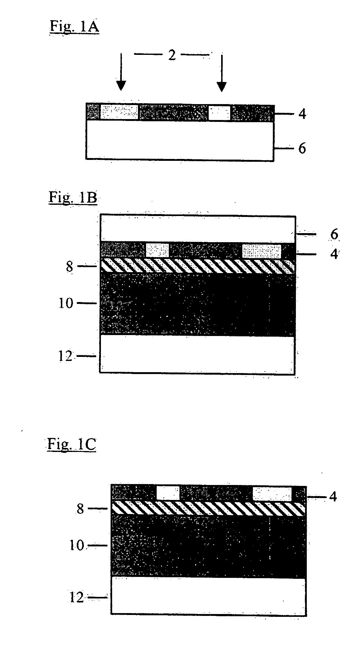
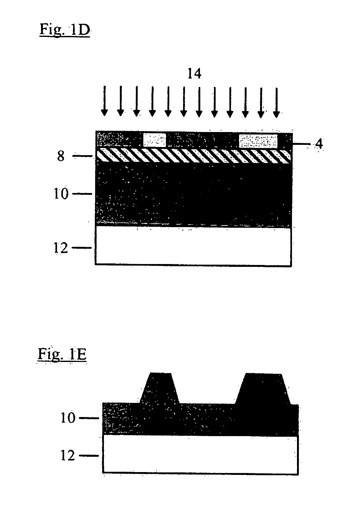
Method of producing a relief image for printing
a relief image and printing technology, applied in the field of printing relief images, can solve the problems of difficult construction, long image creation time, and difficult image printing, and achieve the effects of less time, greater imaging sensitivity, and cost saving
- Summary
- Abstract
- Description
- Claims
- Application Information
AI Technical Summary
Benefits of technology
Problems solved by technology
Method used
Image


Examples
example 1
[0246] A relief image was formed on a flexographic printing plate by the following process. A carrier sheet, formed of 2 mil thick polyethylene terephthalate, was coated with a release layer solution containing of the components listed in Table 1 using a #10 wound-wire coating rod. The resulting article was heated in an 180° F. oven for 3 minutes to form a release layer.
TABLE 1Components and amounts of release layer solution in Example 1ComponentAmount in gramsPVA 52350.0TRITON X-1001.0de-ionized water39.0n-propanol10.0
[0247] A barrier layer solution of the components listed in Table 2 was mixed and applied to the release layer using a #10 wound-wire coating rod. The resulting article was heated in an 180° F. oven for 3 minutes to form a barrier layer.
TABLE 2Components and amounts of barrier layer solution in Example 1ComponentAmount in gramsPCA42.43PC 3640.56FC 44320.30acetone46.51cyclohexanone10.20
[0248] An imageable layer solution of the components listed in Table 3 was mixed...
example 2
[0254] A relief image on a flexographic printing plate was formed in the same manner as in Example 1, except that the carrier sheet was removed from the imaged imageable layer after the flexographic precursor and imaged film were exposed to UV radiation rather than before the flexographic precursor and imaged film were exposed to UV radiation.
[0255] The flexographic printing plates formed by the methods described in Example 1 and in Example 2 were used to print positive 3-point type. Digital Image 1a shows a digital image of the type produced by the flexographic plate formed in Example 1 while Digital Image 1b shows a digital image of the type produced by the flexographic plate formed in Example 2.
Digital Image 1a: Positive 3 Point Type Produced by the Flexographic Plate in Example 1
Digital Image 1b: Positive 3 Point Type Produced by the Flexographic Plate Formed in Example 2
[0256] The flexographic printing plates in Example 1 and in Example 2 were also used to print 30% dots. D...
example 3
[0257] A relief image was formed on a flexographic printing plate by the following process. A carrier sheet, formed of 2 mil thick polyethylene terephthalate, was coated with a release layer solution containing of the components listed in Table 4 using a #10 wire-wound coating rod. The resulting article was heated in an 180° F. oven for 3 minutes to form a release layer.
TABLE 4Components and amounts of release layer solution in Example 3ComponentAmount in gramsMETHOCEL A 15LV3.2TRITON X-1001.0de-ionized water70.8n-propanol25.0
[0258] A barrier layer solution of the components listed in Table 5 was mixed and applied to the release layer using a #10 wire-wound coating rod. The resulting article was heated in an 180° F. oven for 3 minutes to form a barrier layer.
TABLE 5Components and amounts of barrier layer solution in Example 3ComponentAmount in gramsPCA42.43PC 3640.56FC 44320.30acetone46.51cyclohexanone10.20
[0259] An imageable layer solution of the components listed in Table 6 wa...
PUM
| Property | Measurement | Unit |
|---|---|---|
| depth | aaaaa | aaaaa |
| thick | aaaaa | aaaaa |
| thickness | aaaaa | aaaaa |
Abstract
Description
Claims
Application Information