Catheter device

Inactive Publication Date: 2005-10-13
SIEMENS HEALTHCARE GMBH
View PDF6 Cites 48 Cited by
  • Summary
  • Abstract
  • Description
  • Claims
  • Application Information

AI Technical Summary

Benefits of technology

[0005] To reduce the resistance which arises especially in the area of the catheter tip primarily at points where the organ bends, designing catheters to deform using wire sections at the tip is known. Here however it is only ever the farthest end which is actively deformable, the rest of the length of the wire-tip controlled catheter, no matter what variant, can be designed to have any degree of stiffness or flexibility but is not actively deformable. Arranging a magnet on the tip of the catheter is also known so that the alignment of the tip can be adjusted magnetically from outside and the tip can thus be navigated magnetically. However this process too still requires force to be transferred from the end of the catheter distant from the body over the length of the catheter to the tip, to guarantee the forward movement of the instrument

Problems solved by technology

The result of this problem is that specific areas cannot be reached with a catheter, whether it is a normal catheter which for example features a particular function mechanism at its tip, e.g. for stimulation or for boiling away of tissue or for conducting electrical signals, or whether it is an endoscopic catheter.
Th

Method used


Image

  • Catheter device
  • Catheter device
  • Catheter device

Examples


Example

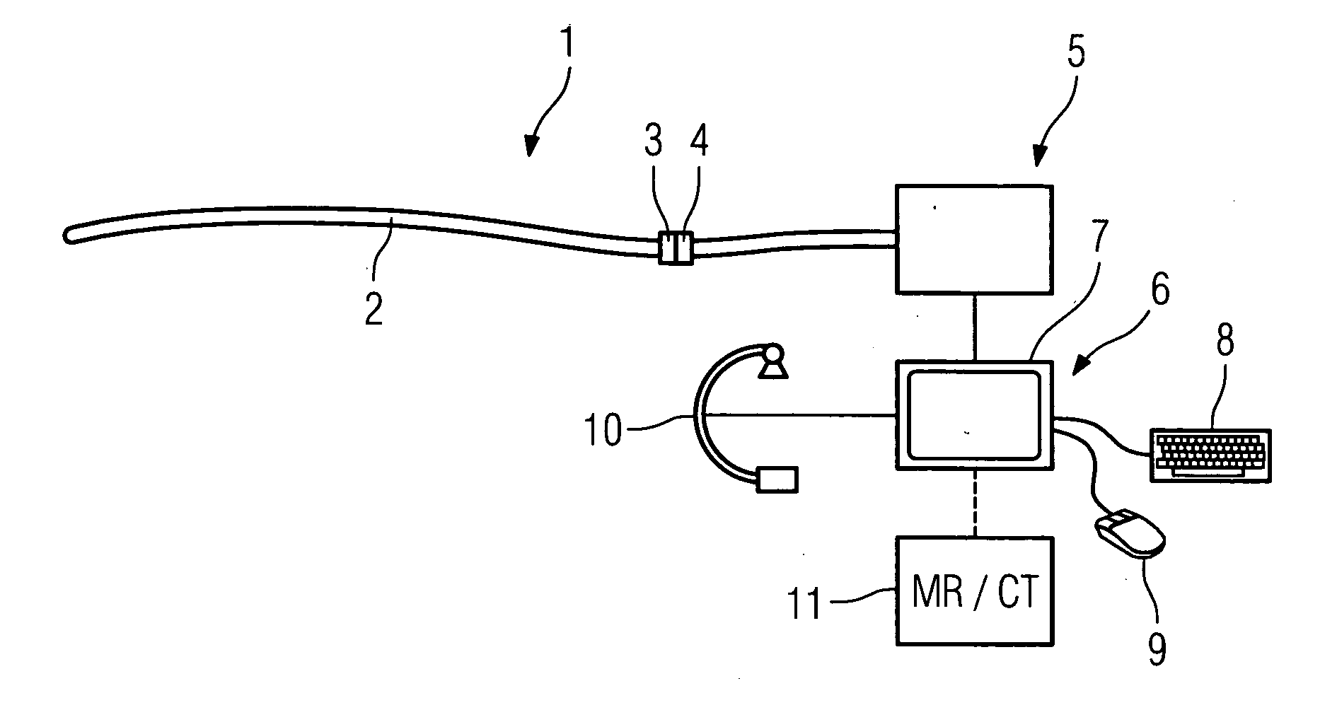
[0023]FIG. 1 shows an inventive catheter device 1 comprising a catheter 2, at the free end of which, the end which is not to be introduced into the patient, a connection device 3 is provided, which is coupled with a connection device 4, which can be controlled by a control device 5, via which the bending elements integrated into the catheter can be controlled. It is possible via control device 5 to activate each individual bending element separately. The bending elements which are arranged distributed along the lengthwise axis of the catheter and along the catheter length are for example tubular hollow bodies to which a liquid or gaseous filler medium can be hydraulically or pneumatically applied, which in their non-loaded state are unfilled and flexible and in their filled state under pressure assume a prespecified relatively rigid shape. These make it possible to bend the catheter explicitly as described in greater detail below. The control device 5 is linked to an input device 6,...


PUM


Abstract

Catheter device, comprising a catheter (2) for introduction into a hollow organ, especially a vessel, with a number of bending elements (12, 12a-12f, 12a′-12e′) arranged around the longitudinal axis of the catheter and distributed over at least a part of the catheter length, which can be activated separately for a specified change of shape via a control device (5), as well as a number of bending sensors (15, 15a-15e, 15a′-15e′) arranged around the longitudinal axis of the catheter and distributed over at least a part of the catheter length communicating with a control device (5), with the control device (5) being embodied to determine the given geometrical shape of the catheter (2) on the basis of the bending sensor signals and to determine the change of shape of the bending elements (12, 12a-12f, 12a′-12e′) necessary for a movement of the catheter (2) by a forward movement length preferably specifiable on the user side to enable the catheter (2) to move by itself at least in part, by explicit bend-dependent force application to the wall of the organ (16).

Description

CROSS REFERENCE TO RELATED APPLICATIONS [0001] This application claims priority to the German application No. 10 2004 017 834.8, filed Apr. 13, 2004 which is incorporated by reference herein in its entirety. FIELD OF INVENTION [0002] The invention relates to a catheter device, comprising a catheter for introduction into a hollow organ, especially a vessel. BACKGROUND OF INVENTION [0003] Catheters, a term which also covers endoscopes in this document, are being increasingly used for intravascular or intercardial treatment, with applications in the gastro-intestinal tract also being possible. To this end the catheter is introduced into the elongated hollow organ, and, following the shape of the organ, it has to negotiate multiple curves in the vessel or the intestine. Following the curves is made easier by making the catheter relatively flexible. This flexibility however makes it more difficult to push the catheter forward manually since such a catheter is as a rule advanced by the do...

Claims


Application Information

Patent Timeline
IPC IPC(8): A61B6/00A61M25/01A61M25/092
CPCA61M25/0105A61M2025/0161A61M25/0155
Inventor BOESE, JANKLEEN, MARTINRAHN, NORBERT
Owner SIEMENS HEALTHCARE GMBH
Why Eureka
Try Eureka