Partially embedded database and an embedded database manager for a control system

Active Publication Date: 2005-10-13
SIEMENS BUILDING TECHNOLOGIES
View PDF9 Cites 2 Cited by
  • Summary
  • Abstract
  • Description
  • Claims
  • Application Information

AI Technical Summary

Benefits of technology

[0015]FIG. 9 is a schematic of a control system similar in most respects to that illu

Problems solved by technology

However, processing power is only useful if adequate memory is available to support the processor when performing tasks.
Unfortunately, economic considerations often dictate the amount of memory installed in a controller, and, as a result, insufficient memory problems may arise.
Such insufficient memory problems often arise, for example, when an existing control system is upgraded or refurbished instead of replaced.
However, the memory required to operate the additional software often exceeds the capacity of the existing memory disposed in the controller.
Unfortunately, modifying memory or any other hardware associated with an existing controller may be too costly to implement.
This problem is further exacerbated when, for example, the control system is a building control system that has been integrated into the design of the building in which the system is installed.
In these cases, a control system upgrade may require modifying the building design, a result that is both costly and typically undesired.
However, the hardware for a controller is often completed before the software required to operate the controller.
However, the amount of memory required to support the final version of the software often exceeds the memory estimations due to the number of advanced features being supplied by today's controllers.
Moreover, designing the hardware at the same time as the software will not necessarily eliminate the problem because, even after system installation, the software associated with a controller often continues to evolve to meet customer demands for additional features.
As a result, control system designers are frequently forced to eliminate features or otherwise reduce the memory requirements of the software that supplies the features.

Method used


Image

  • Partially embedded database and an embedded database manager for a control system
  • Partially embedded database and an embedded database manager for a control system
  • Partially embedded database and an embedded database manager for a control system

Examples


Embodiment Construction

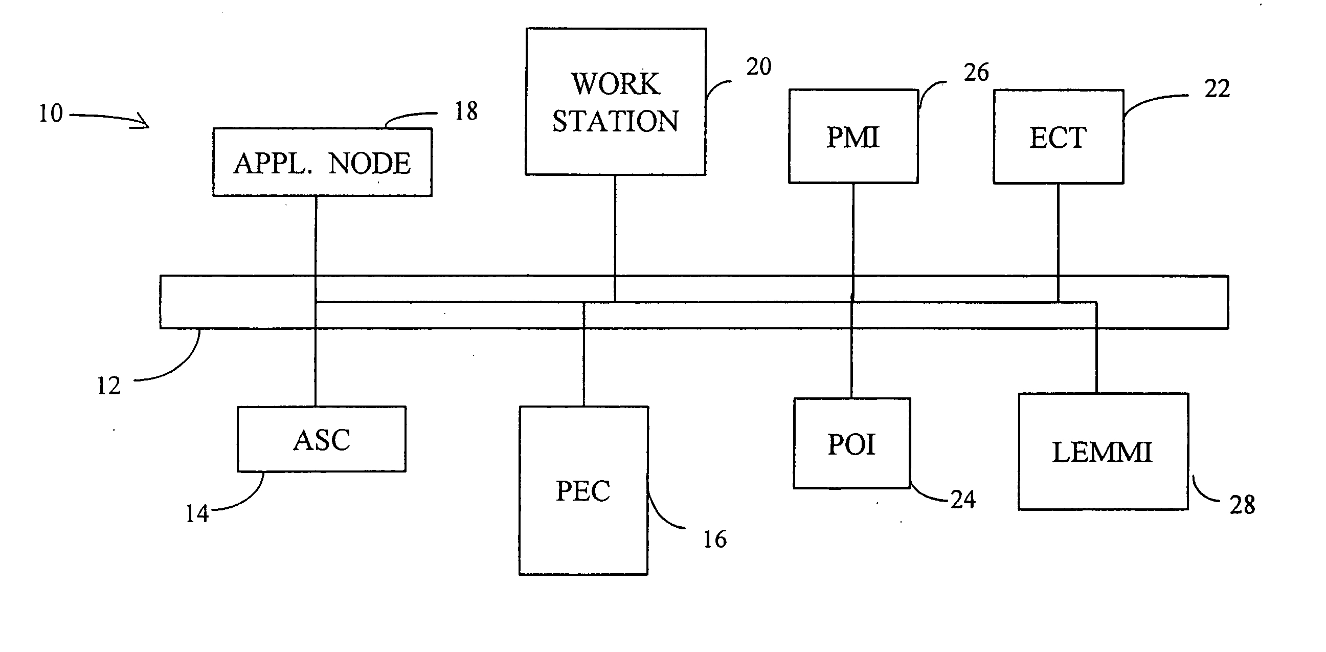
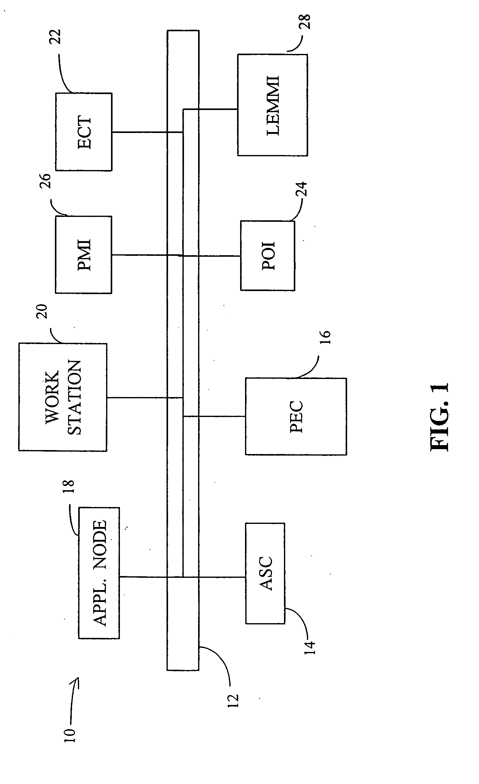
[0018] Referring now to the drawings wherein like reference numerals refer to similar or identical parts throughout the several views, and more specifically to FIG. 1 thereof, a control network 10 for providing, for example, building control includes a communication network 12 to support communication between a set of network control devices including an application specific controller 14, a programmable equipment controller 16, an application node 18, an operator workstation 20, and an engineering and commissioning tool 22. The network control devices may further include a set of interfaces by which an operator may monitor / control the system including a portable operator interface 24, a panel mount interface 26, and a low end human machine interface 28 having a small display and limited features.

[0019] The application specific controller 14 is configured to control a local mechanical and / or electronic device (not shown) associated with a specific application such as, for example, ...


PUM


Abstract

A method is used for editing a data element stored in a static memory device comprising a plurality of storage units. The method includes a step of copying a content of one of the storage units to a dynamic memory device, wherein the content comprises the data element. The method further includes editing the data element while the data element is stored in the dynamic memory. The method also includes erasing said one of the storage units, and writing the content, including the data element that has been edited, into one of the storage units.

Description

[0001] This application is a divisional of, and claims the benefit of, prior application Ser. No. 10 / 054,751, filed Oct. 22, 2001.FIELD OF THE INVENTION [0002] The present invention generally relates to a data storage system for a control system, and more particularly to a database that is partitioned between static and dynamic memory and a database manager that is stored in static memory. BACKGROUND OF THE INVENTION [0003] Control systems are becoming increasingly more computerized. As a result, many of today's controllers include processors for processing control system data. However, processing power is only useful if adequate memory is available to support the processor when performing tasks. [0004] Unfortunately, economic considerations often dictate the amount of memory installed in a controller, and, as a result, insufficient memory problems may arise. Such insufficient memory problems often arise, for example, when an existing control system is upgraded or refurbished instea...

Claims


Application Information

Patent Timeline
IPC IPC(8): G06F17/30
CPCY10S707/99931Y10S707/99932G06F17/30339G06F17/3048Y10S707/99942G06F16/24552G06F16/2282
Inventor SOEMO, MICHAELGAGNER, MARKSTEWART, JOHNPOLLOCK, PHIL
Owner SIEMENS BUILDING TECHNOLOGIES
Why Eureka
Try Eureka