Data mirror cluster system, method and computer program for synchronizing data in data mirror cluster system

a cluster system and data mirror technology, applied in fault response, memory adressing/allocation/relocation, instruments, etc., can solve the problems of increasing the time required to perform data synchronization, and increasing the amount of information to be lost, so as to reduce the amount of data lost, and improve the effect of synchronization speed

Inactive Publication Date: 2005-10-13
NEC CORP
View PDF12 Cites 21 Cited by
  • Summary
  • Abstract
  • Description
  • Claims
  • Application Information

AI Technical Summary

Benefits of technology

[0025] According to the present invention, since data synchronization is obtained by the multiple server apparatuses using the shared memory and the interconnect, the mirror cluster with a small latency can be configured with high speed. This makes it possible to reduce an amount of data to be lost at a trouble occurring time as compared with the conventional case and to improve system availability. Moreover since the shared memory is used by the multiple server apparatuses, management is easy.

Problems solved by technology

However, when a protocol such as TCP / IP is used, a software stack for use in the protocol is deep and communication is performed via an I / O device and the like to cause a problem in which latency is increased.
In the case of the system having a large latency, much time is required to perform data synchronization between the operation server and the standby server.
As a result, when trouble occurs in the operation server to fail over to the standby system, an amount of information to be lost is increased since synchronization with the standby system is not obtained during the trouble, so that merits resulting from combination with the cluster configuration are reduced.
However, in this cluster system, an idea for reducing the latency is not provided.
However, in this configuration, management of the memory address space of the corresponding system and the memory address space of the other system is complicated.
However, in this configuration, management of memory address spaces of two main storage devices is complicated.
Moreover, a DMA controller is required to be initialized at a DMA transfer staring time, so that a bottleneck of latency may occur.
As mentioned above, in the conventional data mirror cluster system, there are problems in that much time is required to perform data synchronization between the operation server and the standby server and management of the memory address spaces is complicated.

Method used


Image

  • Data mirror cluster system, method and computer program for synchronizing data in data mirror cluster system
  • Data mirror cluster system, method and computer program for synchronizing data in data mirror cluster system
  • Data mirror cluster system, method and computer program for synchronizing data in data mirror cluster system

Examples


Embodiment Construction

[0033] A data mirror cluster system according to an embodiment of the present invention will be explained with reference to the drawings.

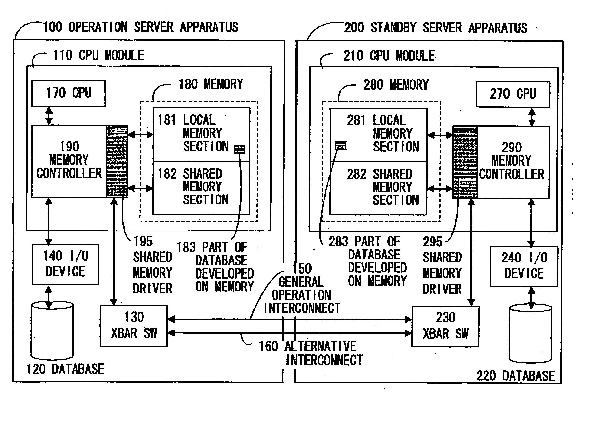
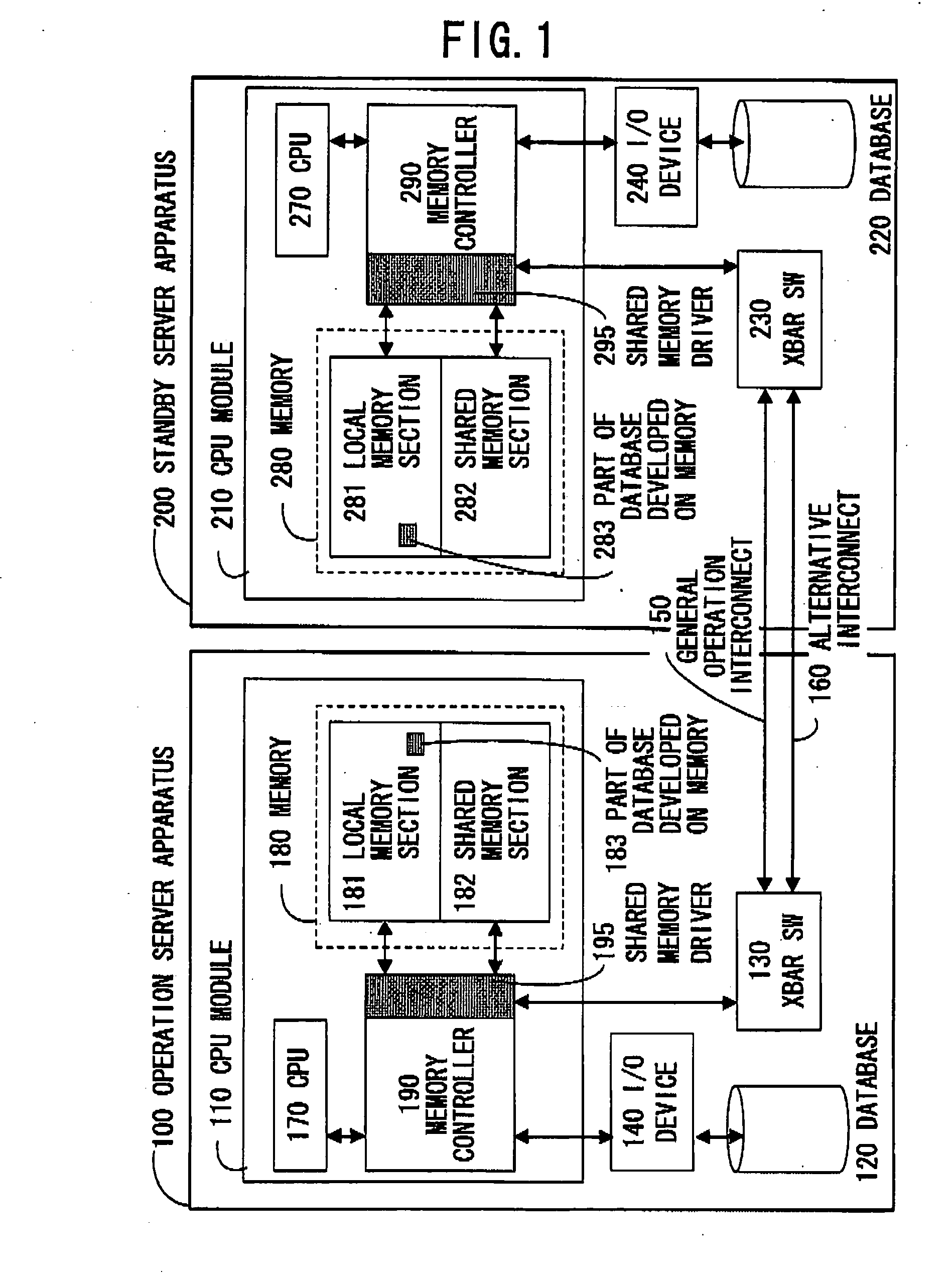
[0034]FIG. 1 is a configuration example of a data mirror cluster system according to an embodiment of the present invention including two server apparatuses 100 and 200. The server apparatuses 100 and 200 have the same hardware configuration. In FIG. 1, the server apparatus 100 is an operation server apparatus and the server apparatus 200 is a standby server apparatus.

[0035] The server apparatuses 100 and 200 are connected to each other by an interconnect that can transfer changed contents of the database possessed by one apparatus and a synchronization signal to the other node (server apparatus) 200 or 100 at high speed. For example, in FIG. 1, the interconnect between the respective nodes is duplexed to improve fault tolerance. In the embodiment of FIG. 1, an interconnect 150 is generally used and an interconnect 160 is used as an alternative. ...


PUM


Abstract

Server apparatuses that configure a data mirror cluster system include databases, shared memories, and memory controllers, respectively. The server apparatuses are connected by interconnects and can directly access communication partner's shared memories via the memory controllers, respectively. One of the server apparatuses operates as an operation server apparatus and the other operates as a standby server apparatus. The memory controller of the operation system updates the database and writes changed data to the shared memory of the standby system. The memory controller of the standby system updates the database of the standby system according to the changed data written to the shared memory of the standby system.

Description

BACKGROUND OF THE INVENTION [0001] 1. Field of the Invention [0002] The present invention relates to a data mirror cluster system and a method for synchronizing data, and particularly to a cluster system and method capable of synchronizing data of multiple servers at high speed. [0003] 2. Description of the Related Art [0004] In the data mirror cluster system, the respective nodes are connected to each other using a connecting section such as LAN and the like as an interconnect to synchronize data between nodes. [0005] However, when a protocol such as TCP / IP is used, a software stack for use in the protocol is deep and communication is performed via an I / O device and the like to cause a problem in which latency is increased. [0006] The interconnect used here is a connecting section, which serves as an input / output interface between an operation server and a standby server (multiple standby servers may be possible) that configure the cluster to synchronize data between the operation ...

Claims


Application Information

Patent Timeline
Patent Type & Authority Applications(United States)
IPC IPC(8): G06F11/00G06F11/20G06F12/00G06F12/02G06F13/14G06F17/30H04L7/00
CPCG06F11/2097G06F11/2056
Inventor KOISHI, TAKAHIRO
Owner NEC CORP
Why Eureka
Try Eureka