Engine air filter and sealing system

a technology of sealing system and engine, which is applied in the direction of machine/engine, filtration separation, separation process, etc., can solve the problems of increasing maintenance costs, increasing the vulnerability to damage from small foreign particles, and premature wear of engine components, so as to reduce loss and non-uniform pressure, the effect of effectively removing contaminants

Active Publication Date: 2005-10-20
DONALDSON CO INC
View PDF20 Cites 50 Cited by
  • Summary
  • Abstract
  • Description
  • Claims
  • Application Information

AI Technical Summary

Benefits of technology

[0004] Among the several objects and features of the present invention that may be noted the provision of an engine intake air filtration system which effectively removes contaminants; the provision of such a system which is usable in existing aircraft without substantial modifications; the provision of such a system which readily permits movement of the engine relative to the surrounding airframe; the provision of such a system which is not adversely affected by unusually high pressures; the provision of such a system which minimizes loss and non-uniformity of pressure to the intake flow; the provision of such a system which is readily accessible for maintenance; the provision of such a system which is lightweight; and the provision of such a system which is economical.

Problems solved by technology

The compressor and turbine are designed with small tolerances between moving parts which maximize efficiency, but which also increase vulnerability to damage from small foreign particles.
Contamination of intake air, even in a small amount, causes premature wear on engine components, increases maintenance costs, and degrades operational reliability.
Unfortunately, aircraft are exposed to contaminants when operating at low altitudes where air is frequently contaminated with material from the ground, such as sand and dust.
That problem is aggravated for helicopters due to rotor downwash and prolonged low-altitude operation.
Effective sealing is difficult to implement and maintain because the engine moves relative to adjacent parts of the airframe as its power setting varies.
Unfortunately, seals have been stiff or insufficiently flexible to move in this way while maintaining airtight integrity.
Further, seals are prone to fail when exposed to strong differential pressures if the engine should experience a surge instability that suddenly increases inlet pressure.

Method used


Image

  • Engine air filter and sealing system
  • Engine air filter and sealing system
  • Engine air filter and sealing system

Examples


Embodiment Construction

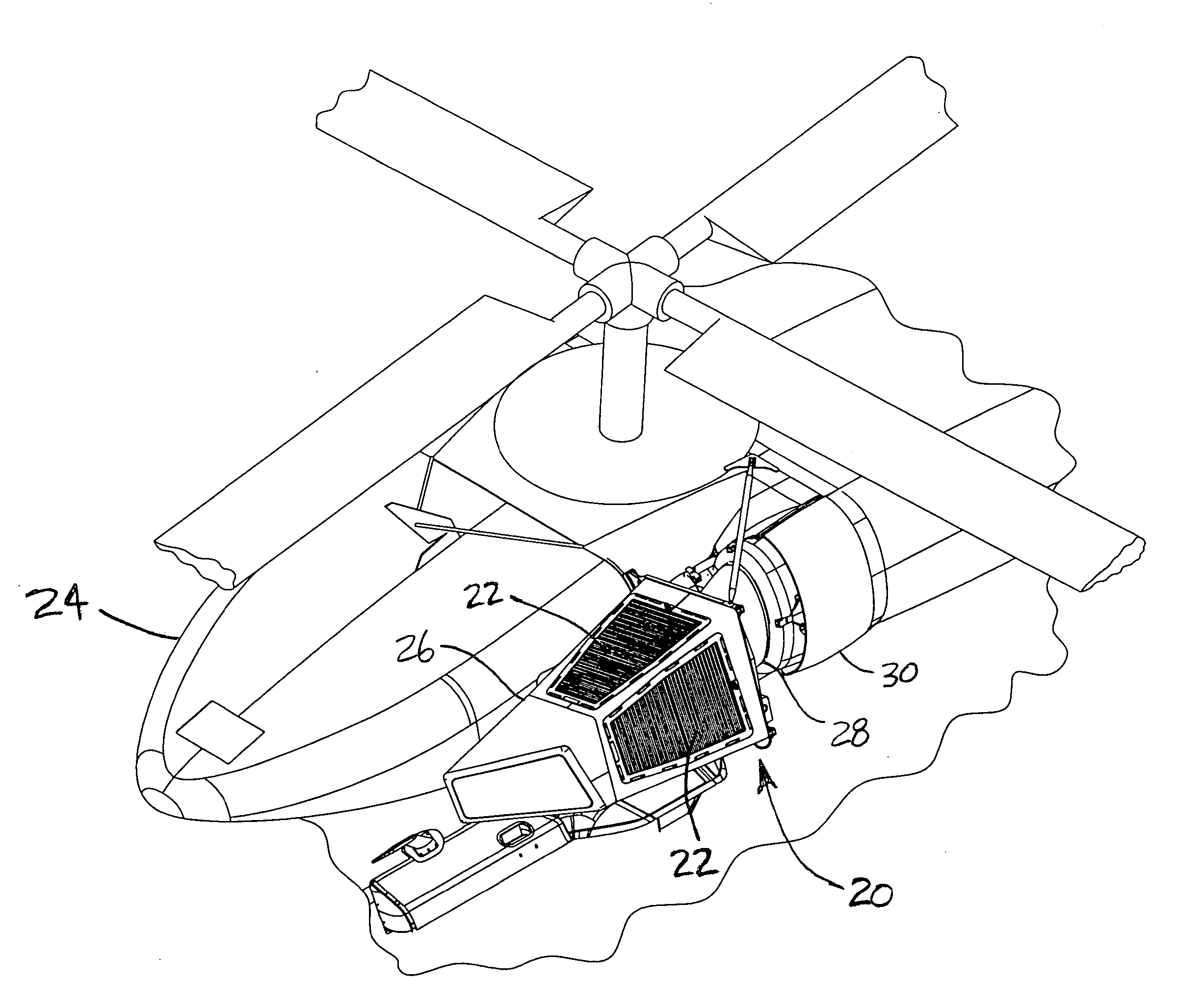
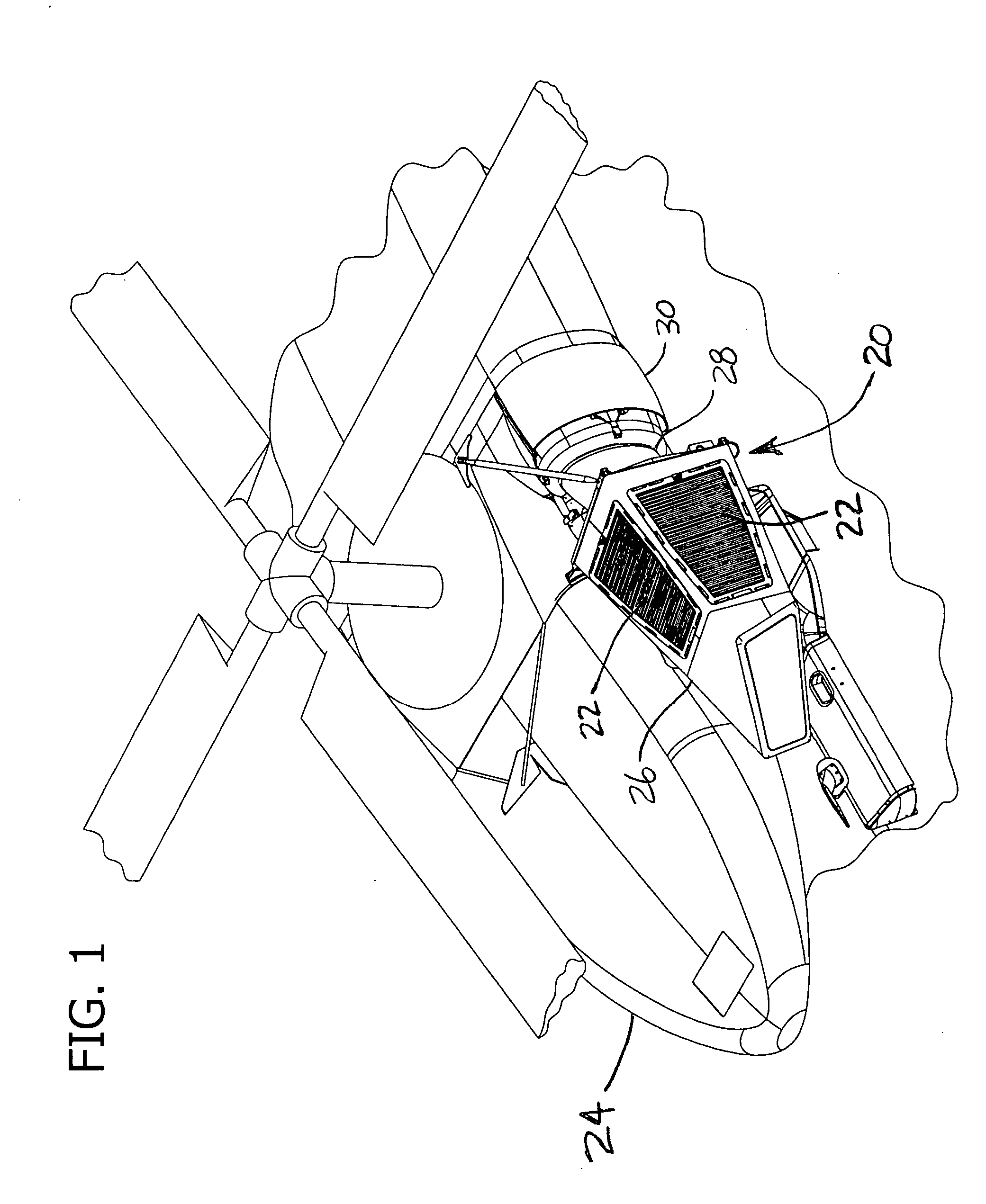
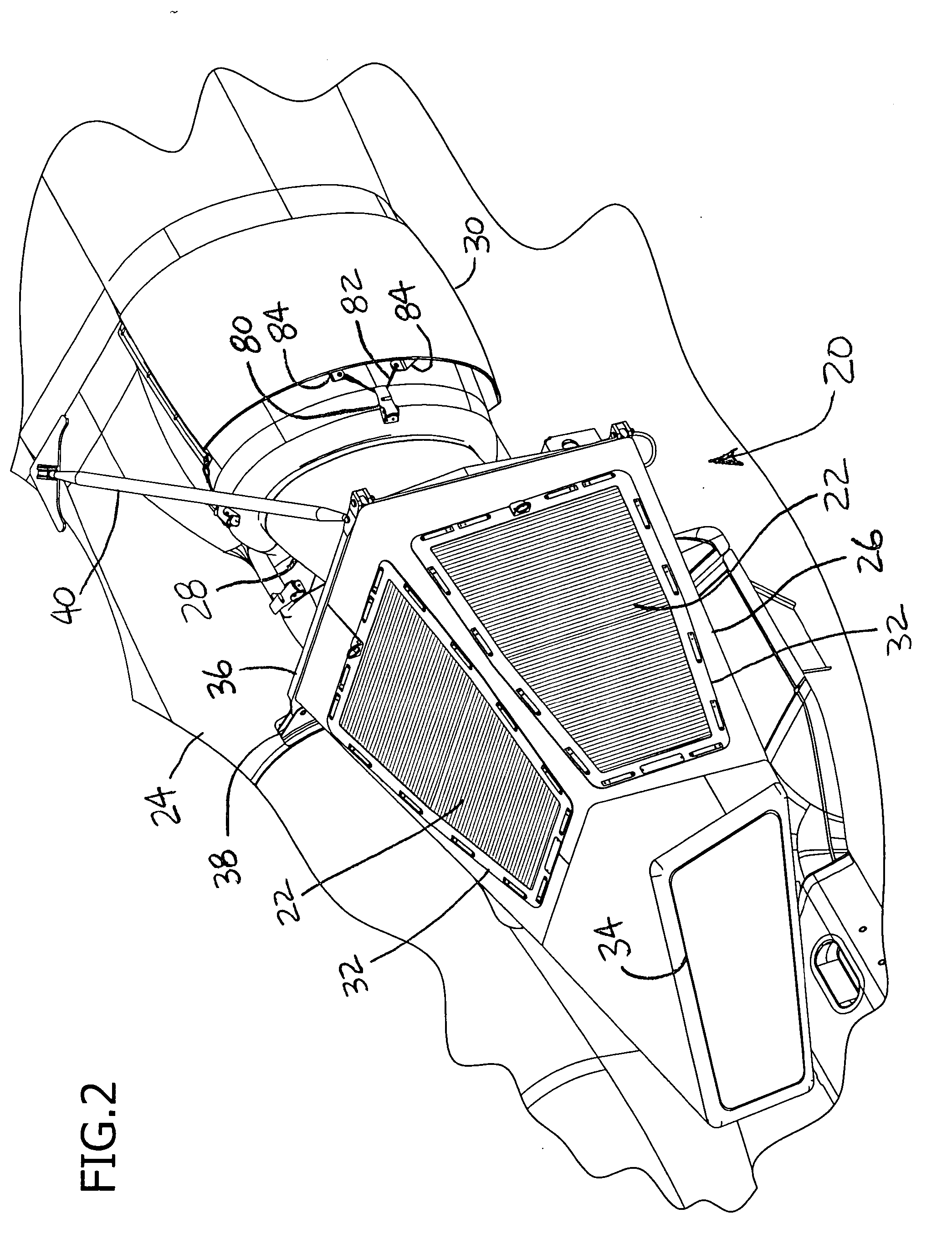
[0021] Referring now to the drawings and in particular to FIG. 1, an air induction system of the present invention is designated generally by 20. The system 20 includes filters 22 for protecting an engine (not shown) from ingestion of contaminant particles. The system is primarily intended for use with a gas turbine engine which is installed in an aircraft 24, such as a UH-60 Blackhawk helicopter. However, it is understood that the system 20 can be used with other types of air-breathing engines, for installation at a facility or factory, or for use on a portable cart, without departing from the scope of this invention.

[0022] The system 20 includes a nacelle 26 and a transition duct 28 which are positioned forward of an inlet 30 and which provide intake air to the inlet for delivery to the engine. There are two such systems 20 aboard the helicopter 24 for two corresponding inlets 30. The nacelle 26 comprises a housing having four outer sides and a hollow interior, each side having a...


PUM

PropertyMeasurementUnit
lengthaaaaaaaaaa
flexibleaaaaaaaaaa
resilientaaaaaaaaaa

Abstract

An air induction system for an engine to remove contaminants from intake air prior to delivery to the engine. The system includes an assembly for filtering air which is mounted in advance of the engine, and a duct for delivering air from the assembly to the engine. A sealing system is provided which prevents entry of unfiltered air while simultaneously permitting movement of the engine relative to adjacent parts of the airframe as engine power setting varies. The seal is protected from high pressures in the duct which can occur in operation of the engine.

Description

BACKGROUND OF THE INVENTION [0001] This invention relates generally to air intakes for engines, and in particular to a system for mounting and sealing a barrier filter which protects an aircraft engine. [0002] An engine for aircraft propulsion requires intake air that is free from contaminants to provide for efficient combustion and avoid internal damage. The compressor and turbine are designed with small tolerances between moving parts which maximize efficiency, but which also increase vulnerability to damage from small foreign particles. Contamination of intake air, even in a small amount, causes premature wear on engine components, increases maintenance costs, and degrades operational reliability. Unfortunately, aircraft are exposed to contaminants when operating at low altitudes where air is frequently contaminated with material from the ground, such as sand and dust. That problem is aggravated for helicopters due to rotor downwash and prolonged low-altitude operation. [0003] Sy...

Claims


Application Information

Patent Timeline
Patent Type & Authority Applications(United States)
IPC IPC(8): B01D46/00B01D46/10B01D46/24B01D46/52B01D50/00
CPCB01D46/0005B01D46/002B01D46/10B01D46/4227B01D46/523Y02T50/672B01D2275/206B64D33/02B64D2033/0246F02C7/052B01D2271/022Y02T50/60B01D46/58
Inventor STELZER, JAMES F.NEWMAN, THOMAS L.
Owner DONALDSON CO INC
Why Eureka
Try Eureka