Hydraulic cylinder, in particular master cylinder for a hydraulic clutch actuation system for motor vehicles

Inactive Publication Date: 2005-10-20
FTE AUTOMOTIVE GMBH & CO KG
View PDF4 Cites 3 Cited by
  • Summary
  • Abstract
  • Description
  • Claims
  • Application Information

AI Technical Summary

Benefits of technology

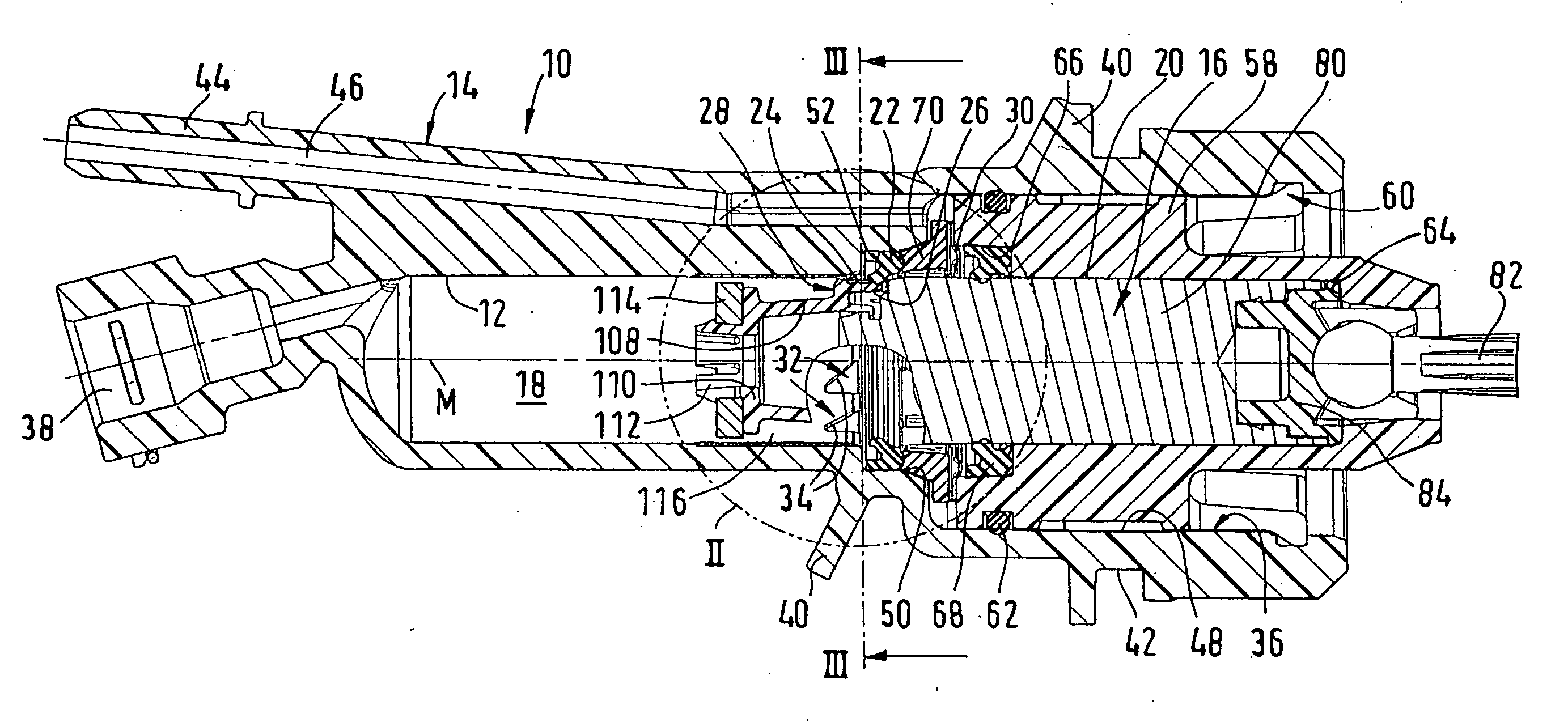
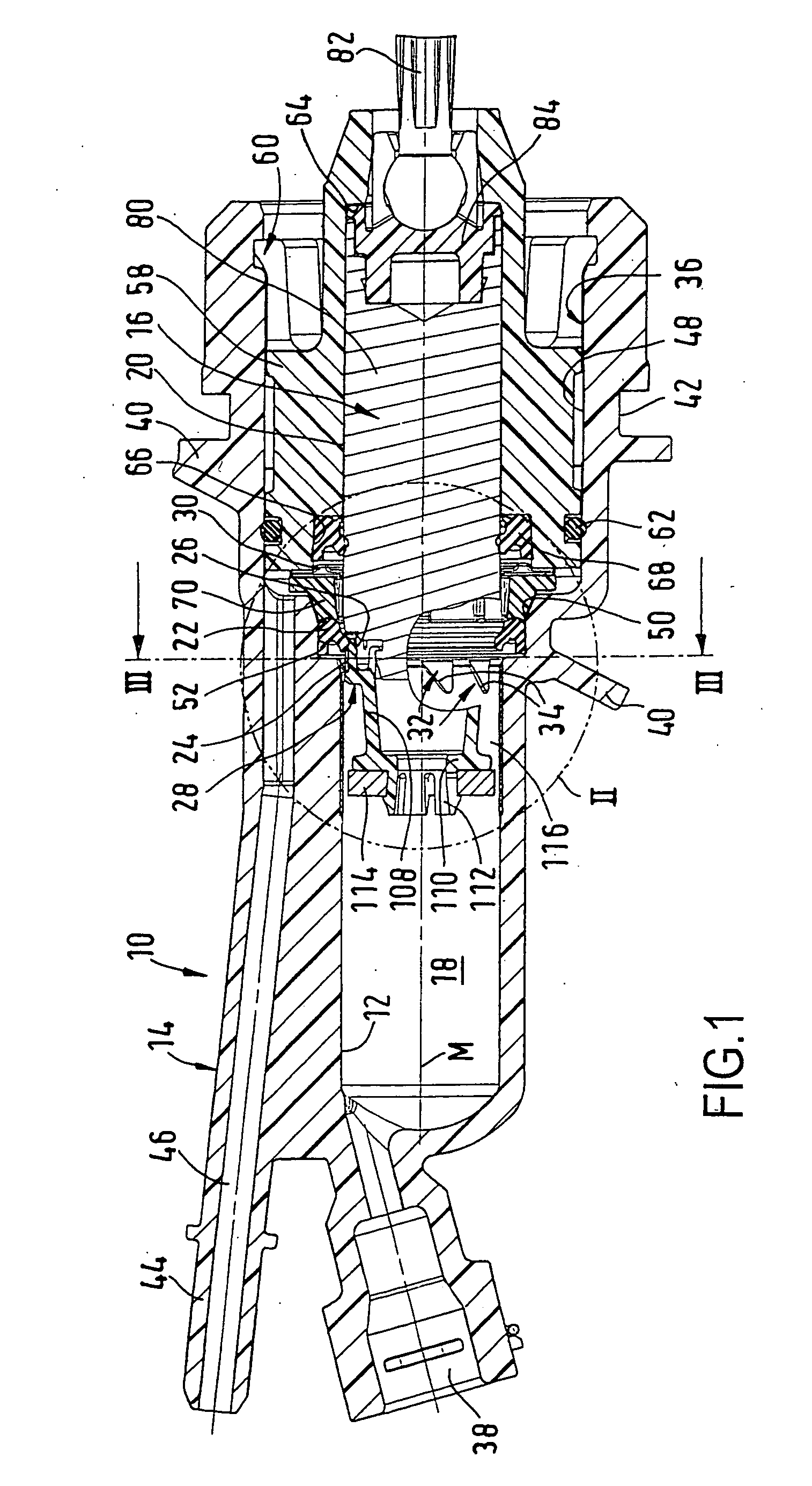
[0009] According to one fundamental concept of the invention, therefore, (at least) in a region of the hydraulic cylinder which is critical with regard to deaeration or degassing, that is to say a lower region in the installed position of the cylinder at the piston-side end of the cylinder wall of the housing, which particularly in the case of a plunger piston having at the end an extension which projects into the pressure chamber, as known for example from DE 202 08 568 U1, is typically covered in the axial direction by the plunger piston or the extension thereof even in the rest position of the plunger piston, profiled 
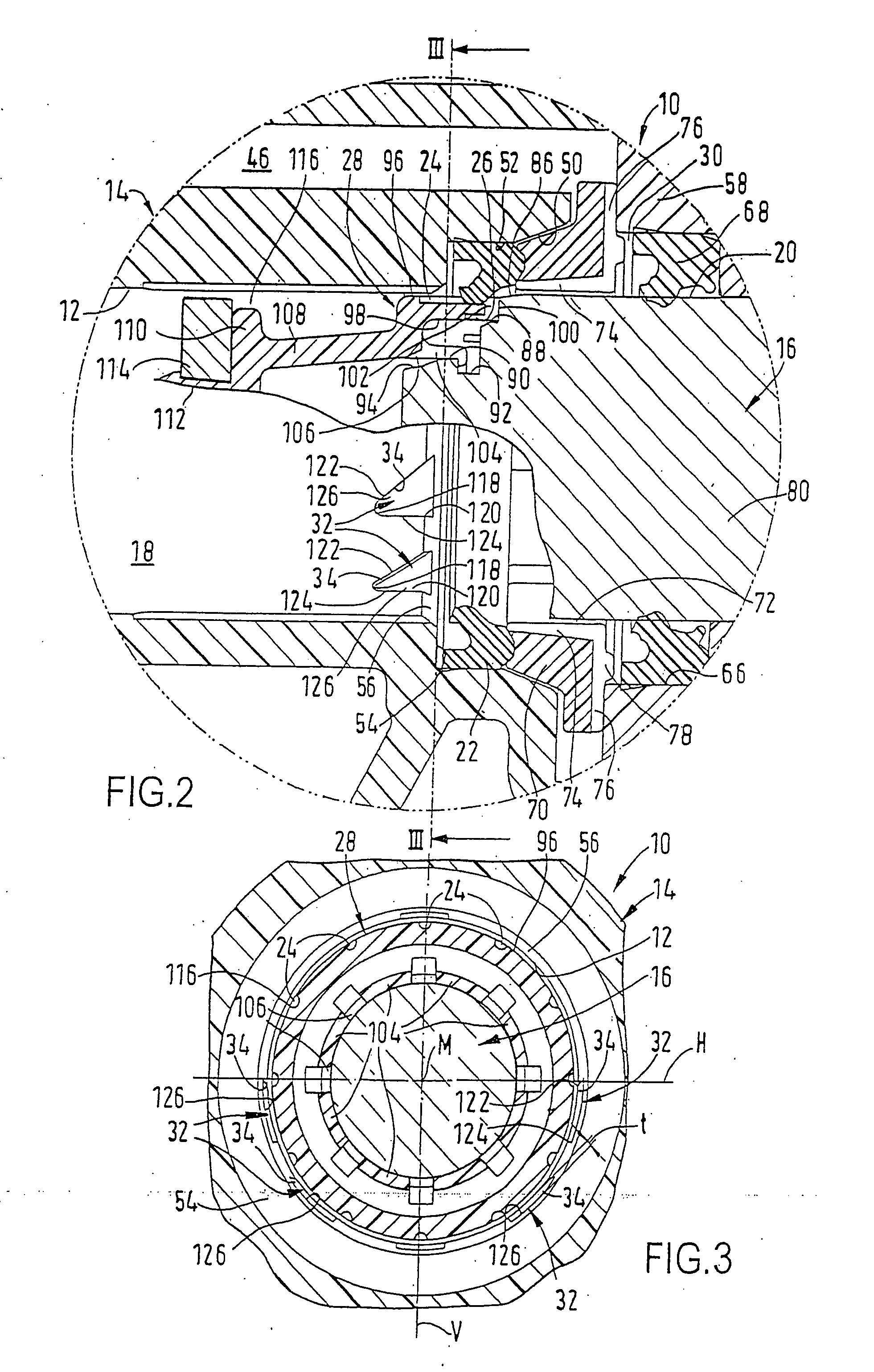
cut-outs are provided which serve to receive fine air or gas bubbles. In this case, the profiled cut-outs act almost as crystallization centers, in which the fine air or gas bubbles can combine to form somewhat larger bubbles of greater lift which thus usually cannot be produced in the annular gap or clearance between the actual cylinder wall and the plunger piston or the extension thereof. Since each profiled cut-out is moreover delimited at the top by a boundary surface which in the installed position of the cylinder rises up towards the equalization grooves of the after-running device, the profiled cut-outs furthermore act as a rising aid for the air or gas bubbles, which can thus easily rise towards the equalization grooves of the after-running device despite the flow or flushing effects in the pressure chamber which as mentioned above are only very small. This therefore ensures, in a conceivably simple manner, better and faster deaeration or degassing of the pressure chamber of the hydraulic cylinder.
[0010] Advantageously, the profiled cut-outs, seen in a developed view of the cylinder wall, each have essentially the shape of a triangle, the longest side of which is formed by the respective upper boundary surface. Although other shapes for the profiled cut-outs are also conceivable, the triangular shape is a shape that can be more easily produced in comparison with, for example, profiled cut-outs which have curved boundary surfaces.
[0012] If the upper boundary surface and / or the lower boundary surface of each profiled cut-out forms an edge with the cylinder wall of the housing, that is to say no rounded surface transition exists there, at this point the breakaway resistance for air or gas bubbles is advantageously minimized, so that in particular even small bubbles of weak lift can detach more easily from the wall surfaces and rise towards the equalization grooves of the after-running device.
[0013] In a further embodiment of the invention, the upper boundary surface and / or the lower boundary surface of each profiled cut-out may advantageously enclose an angle of greater than or equal to 90° with an imaginary tangent placed against the cylinder wall of the housing at right angles to the center axis of the cylinder wall. No undercuts are thus produced here which could make manufacture of the cylinder housing more difficult.
[0014] Furthermore, a larger-diameter cylinder section for receiving the housing-side sealing element may adjoin the piston-side end of the cylinder wall of the housing, said larger-diameter cylinder section being connected to the cylinder wall via an annular shoulder and possibly a bevel, wherein the profiled cut-outs may end in the bevel or the annular shoulder. In such an embodiment, the profiled cut-outs are thus advantageously open towards the rear, that is to say in the direction of the piston, and this further promotes the transporting-away of air or gas bubbles in the hydraulic fluid towards the after-running region.
[0016] Continuing the concept of the invention, the profiled cut-outs may be arranged in a mirror-symmetrical manner with respect to an imaginary plane which contains the center axis of the cylinder wall and runs essentially vertically in the installed position of the cylinder, and this ensures equally good dissipation, in both circumferential directions, of air or gas bubbles from the lower region of the pressure chamber in the installed position of the cylinder.

Problems solved by technology

If, however, the pressure chamber is insufficiently deaerated or degassed, inter alia an undesirable “soft pedal feeling” is produced with a loss of stroke during pedal travel.
However, it has been shown that such a configuration is unsatisfactory for sufficient deaeration in particular of those hydraulic cylinders in which the plunger piston has at its end an extension which projects into the pressure chamber, for example is provided with a retaining cap which serves to store a signal element, for example a ring magnet for sensing the axial piston position, as known for example from DE 202 08 568 U1 by the Applicant.

Method used


Image

  • Hydraulic cylinder, in particular master cylinder for a hydraulic clutch actuation system for motor vehicles
  • Hydraulic cylinder, in particular master cylinder for a hydraulic clutch actuation system for motor vehicles
  • Hydraulic cylinder, in particular master cylinder for a hydraulic clutch actuation system for motor vehicles

Examples


Embodiment Construction

[0023] FIGS. 1 to 3 show, by way of example for a hydraulic cylinder, a master cylinder 10 for a hydraulic clutch actuation system for motor vehicles in the uninstalled, non-actuated state. The master cylinder 10 comprises a housing 14 having a cylinder wall 12, in which housing a piston 16 is received in a longitudinally displaceable manner. The piston 16 together with the cylinder wall 12 delimits a pressure chamber 18 in the housing 14 and, as a plunger piston, has a running surface 20 for a housing-side primary sealing element 22 which—like the other rubber-elastic components of the master cylinder 10—is shown in the non-deformed state for the sake of simplicity. In an operating position (not shown) of the piston 16, in which the primary sealing element 22 is located above the running surface 20 of the piston 16, said primary sealing element cooperates with the running surface 20 in order to seal off the pressure chamber 18 so that a pressure can be built up in the pressure cham...


PUM


Abstract

A hydraulic cylinder, in particular a master cylinder for a hydraulic clutch actuation system for motor vehicles, comprises a housing having a cylinder wall, in which housing a piston is received in a longitudinally displaceable manner. The piston, together with the cylinder wall, delimits a pressure chamber and has a running surface for a housing-side sealing element which in an operating position of the piston co-operates with the running surface thereof in order to seal off the pressure chamber, whereas the pressure chamber in a rest position of the piston is connected to an after-running region by equalization grooves of an after-running device. The cylinder wall of the housing is provided with profiled cut-outs on its piston-side end at least in a lower region in the installed position of the cylinder, which cut-outs each have an upper boundary surface which in the installed position of the cylinder rises up to the equalization grooves of the after-running device. As a result, a hydraulic cylinder of simple design is provided which has an improved deaeration behavior compared to the prior art.

Description

TECHNICAL FIELD [0001] The present invention relates to a hydraulic cylinder. In particular, the invention relates to a master cylinder for a hydraulic clutch actuation system for motor vehicles, as used in motor vehicle construction. PRIOR ART [0002] A generic hydraulic cylinder is known from U.S. Pat. No. 6,584,771 by the Applicant. In these hydraulic cylinders, a pressure is generated in the pressure chamber when the piston undergoes axial relative displacement with respect to the cylinder housing by virtue of force being exerted by a plunger rod articulated for example on a pedal. By virtue of this pressure, a clutch slave cylinder which is hydraulically connected to the hydraulic cylinder is acted upon, which clutch slave cylinder is effectively connected to the clutch in order to disengage the clutch. [0003] The hydraulic cylinders considered here have a piston—also referred to as a plunger piston on account of its design—with a running surface for (at least) one sealing eleme...

Claims


Application Information

Patent Timeline
IPC IPC(8): B60T11/16B60T11/236F16D25/08F16D25/12F16D48/02
CPCB60T11/236F16D25/088F16D2025/081F16D48/02F16D25/12F16D2048/0212F16D25/08
Inventor TROSTER, RUDOLF
Owner FTE AUTOMOTIVE GMBH & CO KG
Why Eureka
Try Eureka