

Liquid filled less lethal projectile
a technology of less lethal projectiles and liquid filling, which is applied in the direction of projectiles, weapons, training ammunition, etc., can solve the problems of serious damage and achieve the effect of stable fligh
- Summary
- Abstract
- Description
- Claims
- Application Information
AI Technical Summary
Benefits of technology
Problems solved by technology
Method used
Image

Examples
Embodiment Construction
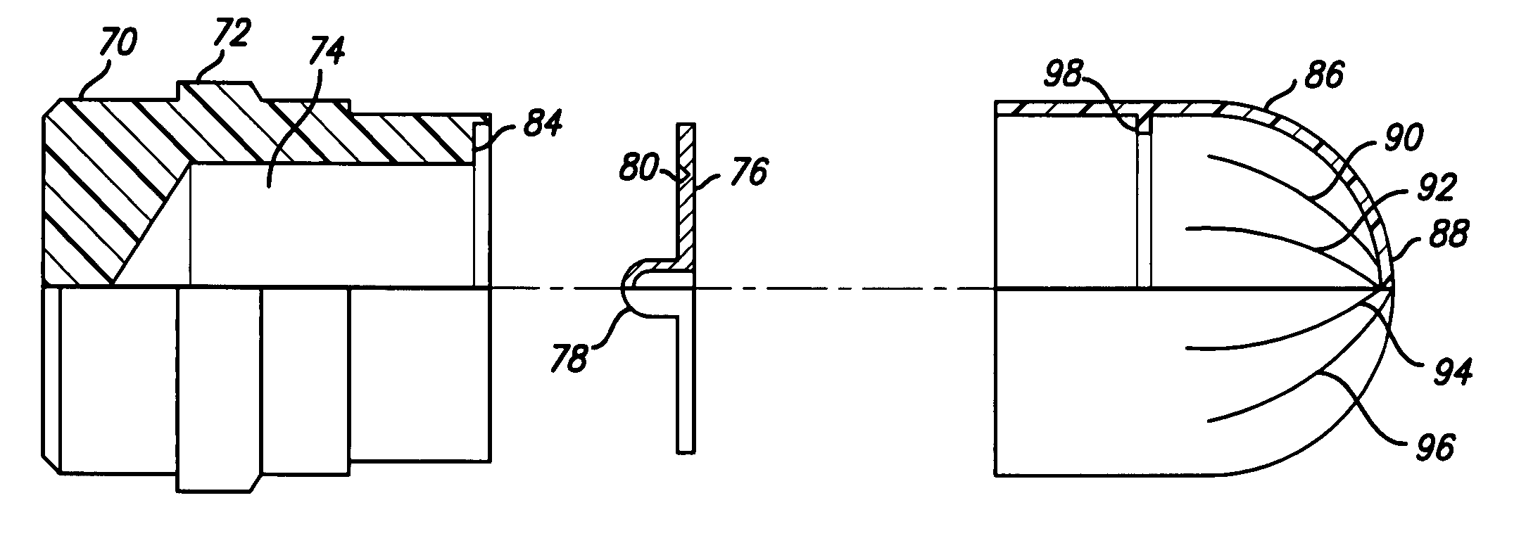
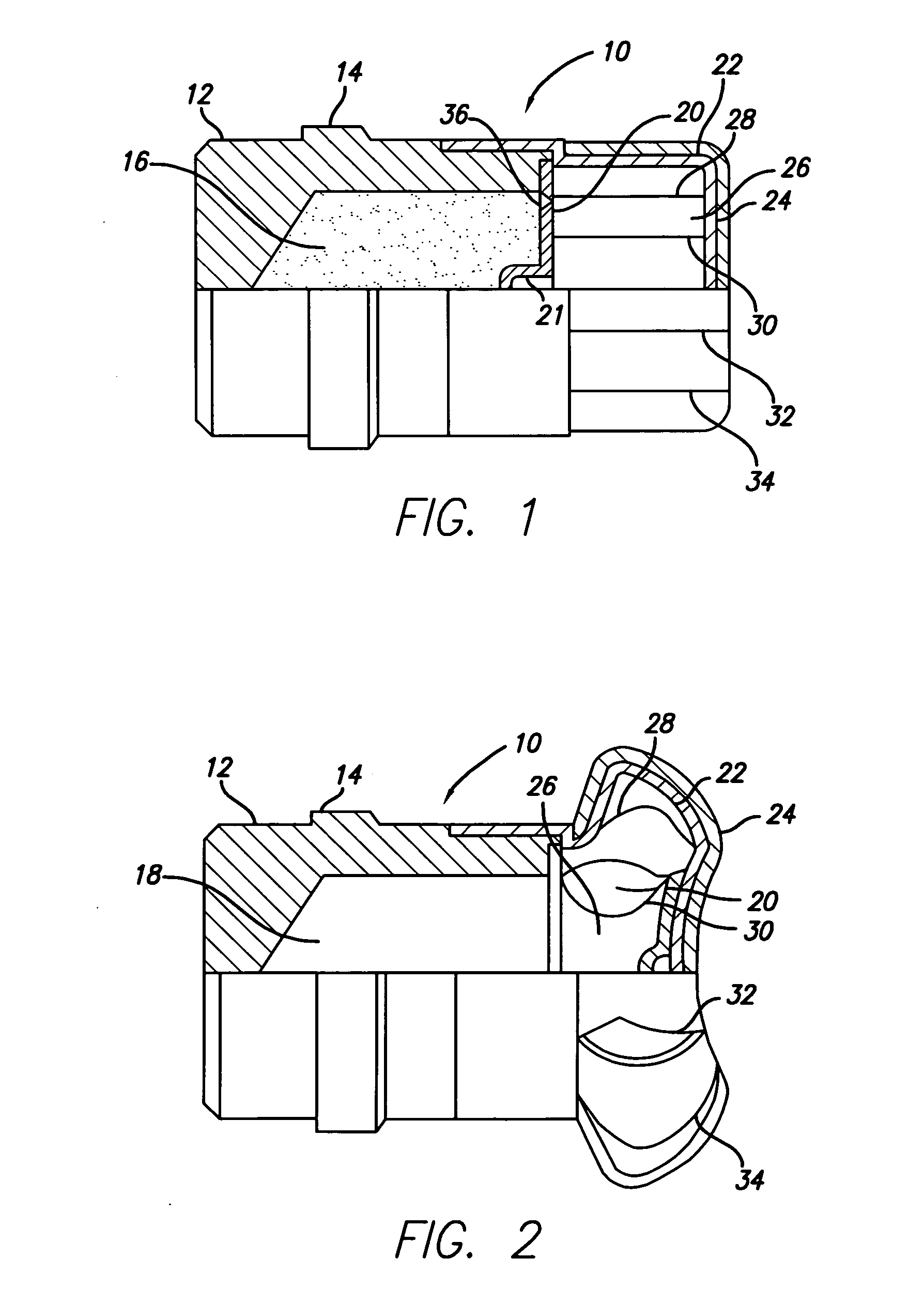
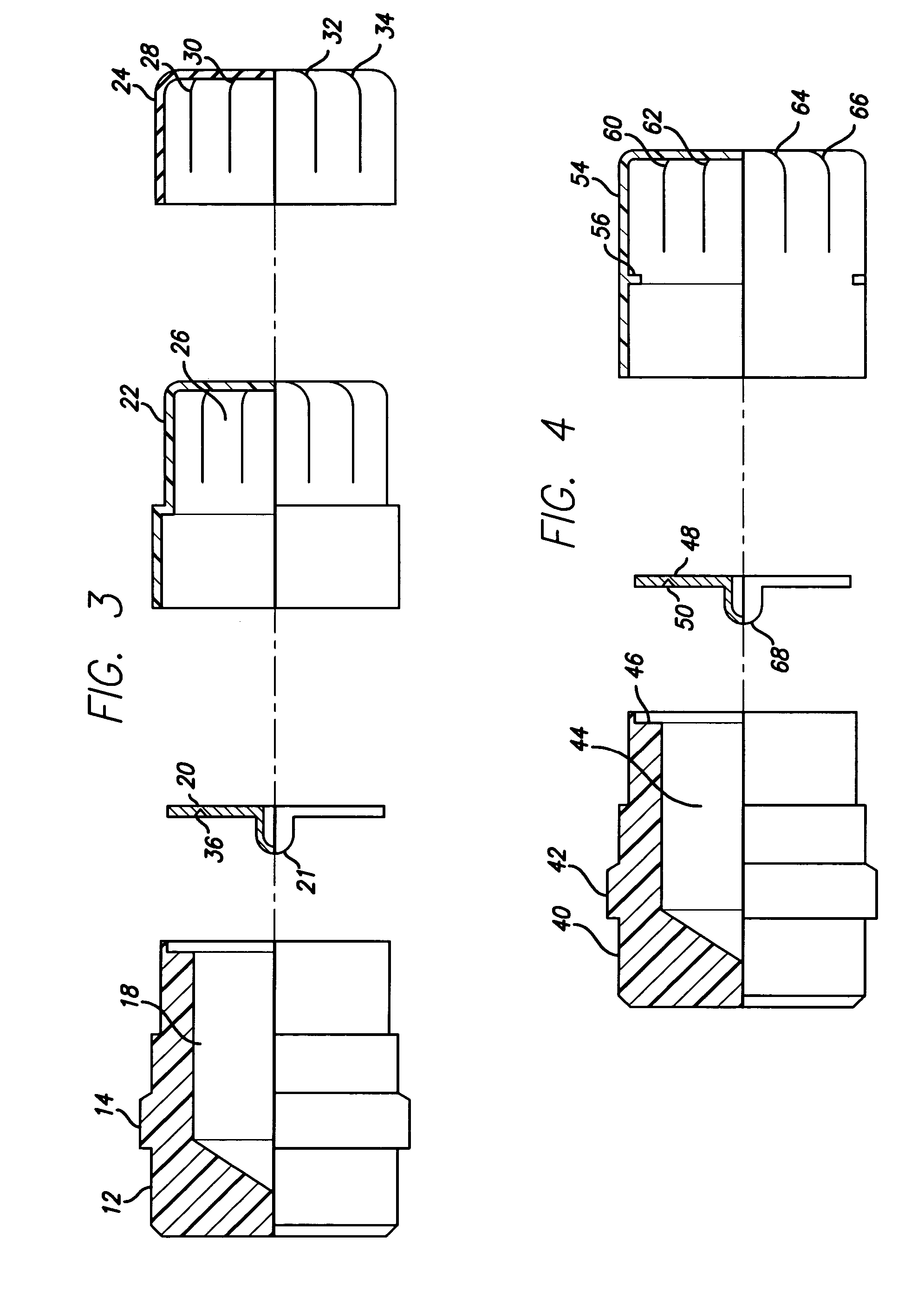
[0022] Referring now to the drawings, there is shown in FIGS. 1, 2, and 3, a projectile 10 having a body 12 with rotating band 14 integral to the body 12. A supply of fluid 16 is contained within a cavity 18 inside of body 12. A frangible closure disk 20 holds fluid 16 in cavity 18. Frangible closure disk 20 has a circular groove 36, which provides a weak point, allowing closure disk 20 to break loose more easily on impact.
[0023] Frangible disk 20 has a small cylindrical projection 21 which projects into fluid cavity 18. Projection 21 acts as an expansion volume, molded into disk 20, where the fluid can expand, if the fluid is exposed to high storage temperatures. This expansion area is necessary, as fluid expansion, if not allowed for, would rupture disk 20 prior to launch or prior to impact.
[0024] An inner, hard-nosed cap 22 is attached to body 12 by an adhesive at assembly. An outer soft-nosed cap 24 covers hard-nosed cap 22. Soft-nosed cap 24 is bonded to hard-nosed cap 22 at ...
PUM
 Abstract
Description
Claims
Application Information