Secondary electron detector, especially in a scanning electron microscope

a scanning electron microscope and electron detector technology, applied in the field of scanning electron microscopes, can solve the problems of practically impossible precision microscopy, practically impossible to carry out non-destructive analysis of specimens, and difficult to handle specimens in vacuum

Inactive Publication Date: 2005-10-20
TESCAN
View PDF10 Cites 14 Cited by
  • Summary
  • Abstract
  • Description
  • Claims
  • Application Information

AI Technical Summary

Problems solved by technology

The handling of a specimen within a vacuum presents a lot of problems.
Nonconductive samples within a vacuum accumulate static charges on their surface, making thus precision microscopy practically impossible.
This problem would be solved by coating such specimens, which, in some specimens such as semiconductors, may entail their destruction and thus it is practically impossible to carry out their nondestructive analysis.
The evident disadvantage this arrangement suffers is the impossibility of simultaneously optimizing the pressure within the specimen chamber and the pressure in the detector chamber.
If, in consideration of the biological samples and their survival within the vacuum, the pressure is maintained at a higher level, the conditions necessary for the operation of the detector are generally insufficient and, vice versa, if the vacuum in the specimen chamber is established to an optimum value for the detector operation, the biological samples do not survive and no non-destructive observation can be performed.
Nevertheless, this system has not solved thoroughly the problem of choking the secondary electrons signal by the back-scattered electrons signal.
In addition to it, the photon signal is usually very weak and the quality of the produced image is low.
The disadvantage of this system is that it does not sufficiently differentiate between secondary electron signal that gives a topographical information and a backscattered electrons signal that gives an information about the material of the specimen.
Another disadvantage is that the Al foil is too thin, about 7,5 nm, and is thus vulnerable to a damage in use.
Further disadvantage is that the foil is in the specimen chamber environment easily contaminated and considering how thin the foil is, the contamination layer acquires soon a thickness comparable with the thickness of the foil, what results in worse penetrability of low energy secondary electrons without influencing high energy backscattered electrons and thus in a worse efficiency of signal collection.

Method used


Image

  • Secondary electron detector, especially in a scanning electron microscope
  • Secondary electron detector, especially in a scanning electron microscope
  • Secondary electron detector, especially in a scanning electron microscope

Examples


Embodiment Construction

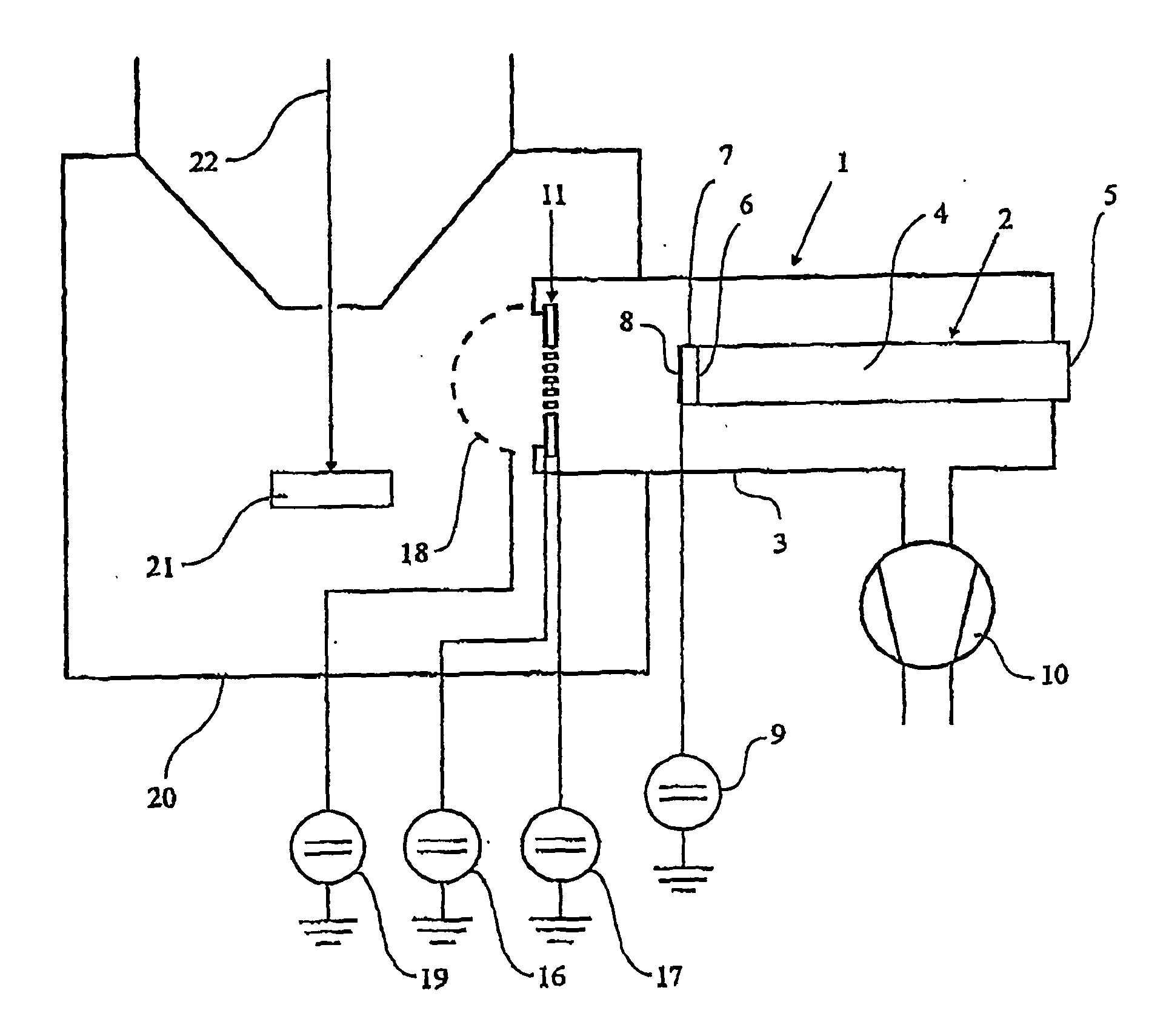
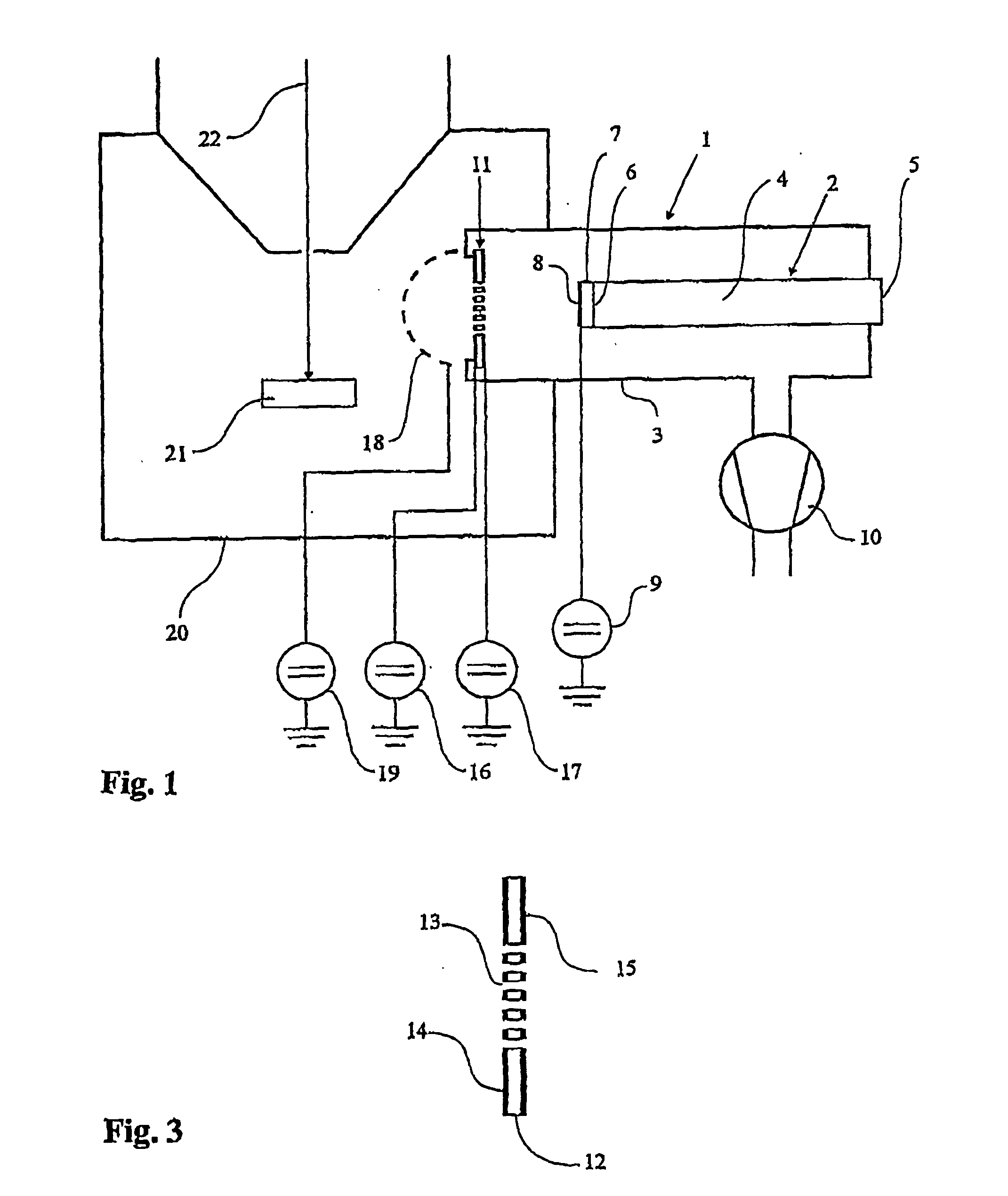
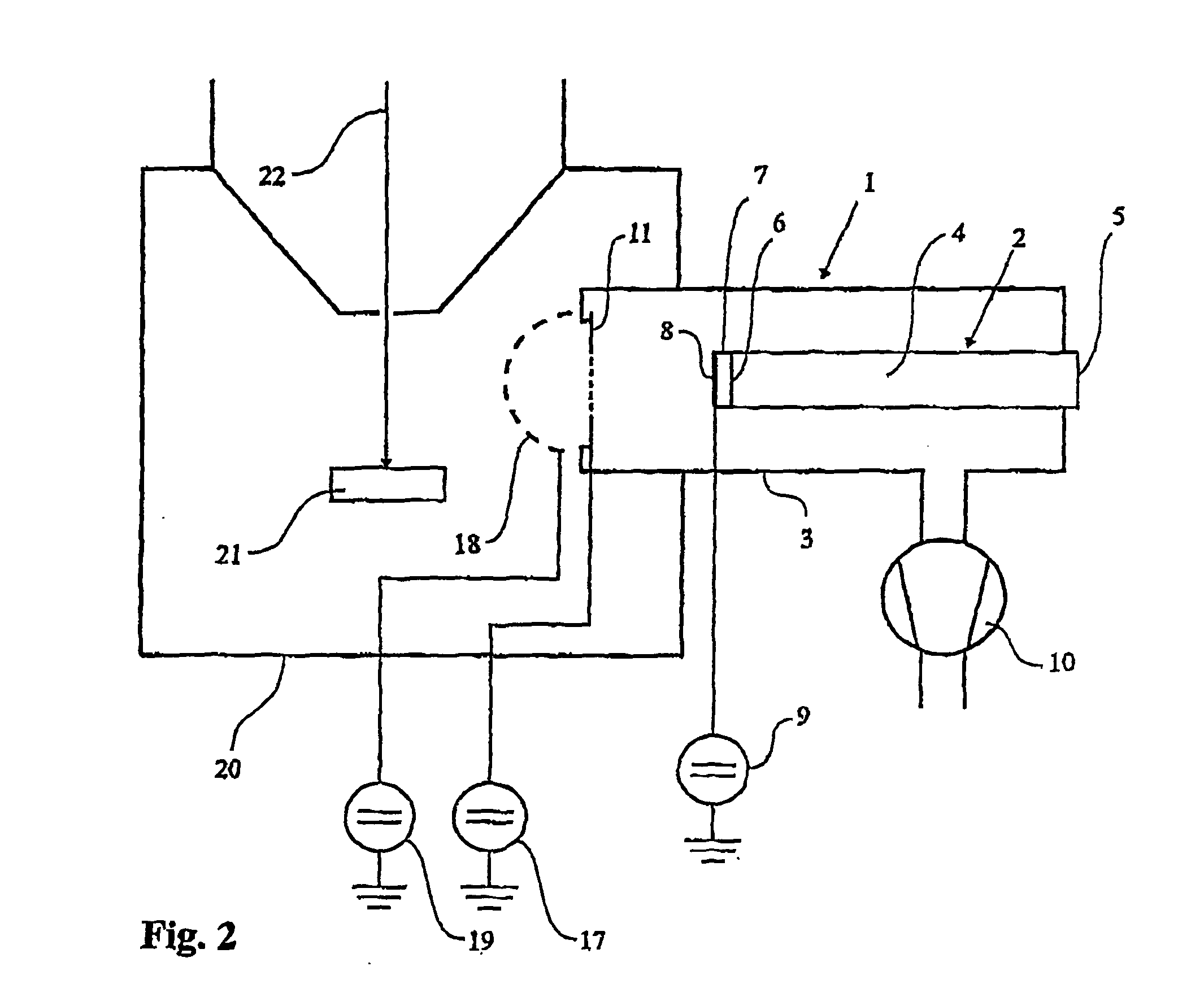
[0024]FIG. 1 shows the first exemplified embodiment of the secondary electron detector according to the present invention. The secondary electrons detector 1 consists of the sensor 2 located in the chamber 3 of the detector. The sensor 2 consists of the light guide 4 to whose output 5 the photo-multiplier (not shown) is connected and to whose output 6 the scintillator 7 is connected, whose surface is coated, while to the coating 8 of the scintillator 7 the high voltage source 9 is connected. To the detector chamber 3 vacuum air pump 10 is connected to create vacuum inside the detector chamber 3. The wall of the detector chamber 3 near to the scintillator 7 is enclosed by an electrically conductive grid 11 constructed from diaphragm 12, in the given embodiment of capton, with orifices 13 and fitted on both sides with conducting coatings 14 and 15. The configuration of capton diaphragm 12 is shown in detail in FIG. 3. To both conducting coatings 14, 15 voltage sources 16, 17 are conne...


PUM

PropertyMeasurementUnit
bias voltageaaaaaaaaaa
voltageaaaaaaaaaa
voltageaaaaaaaaaa

Abstract

The present invention deals with a secondary electron detector (1), especially in a scanning electron microscope. The subject matter of the invention provides a secondary electrons detector (1) constituted by a sensor (2) located in a detector chamber (3), to which a vacuum air pump (10) is connected to produce vacuum inside the detector chamber (3), the detector chamber (3) being in its wall near to the active surface of the sensor (2) enclosed with a diaphragm featuring high resistance to the transmission of gas and low resistance to the transmission of the electrons. The electrically conductive grid (11) is produced either in the form of a copper screen or as a kapton membrane (12) with orifices (13) and it is equipped on both sides with conductive coating (14, 15). Outside the detector chamber (3), the electrically conductive grid (11) is covered with an input screen (18), which is usually of hemispherical shape and is connected to the low voltage source (19) of 80 to 150 V.

Description

FIELD OF THE INVENTION [0001] The invention relates to a secondary electron detector, especially in a scanning electron microscope. BACKGROUND OF THE INVENTION [0002] To create an image of a specimen by means of a scanning electron microscopy, a sample is scanned by an electron beam. Secondary electrons that are emitted from the sample by the striking electron beam are detected and by this signal a synchronously scanned electron beam in a monitor is modulated. The scanning usually takes place within a vacuum, especially to enable the action of both the electron gun and the electron detector. [0003] The handling of a specimen within a vacuum presents a lot of problems. The biological specimens not survive within a vacuum, wet specimens evaporate before an exact image can be produced. An observation of specimens from which different gaseous substances may leak within a vacuum of the microscope should be carefully considered in advance. Nonconductive samples within a vacuum accumulate ...

Claims


Application Information

Patent Timeline
Patent Type & Authority Applications(United States)
IPC IPC(8): H01J37/244
CPCH01J37/244
Inventor JACKA, MARCUSZADRAZIL, MARTINLOPOUR, FILIP
Owner TESCAN
Why Eureka
Try Eureka