Wind turbine mounted on power transmission tower

a technology of wind turbines and power transmission towers, applied in wind energy generation, motors, sustainable buildings, etc., can solve the problems of reducing the overall cost-effectiveness of wind power generation, occupying large tracts of land, and reducing the cost of purchasing or leasing land, so as to reduce the cost of building, reduce the visual and aesthetic impact on the environment, and reduce the cost of line losses.

Inactive Publication Date: 2005-10-20
BRUNET ANDRE
View PDF51 Cites 52 Cited by
  • Summary
  • Abstract
  • Description
  • Claims
  • Application Information

AI Technical Summary

Benefits of technology

[0014] By mounting wind turbines directly on top of power transmission towers, clean, “environmentally friendly” electricity can be generated without any substantial increase in power grid infrastructure. By implementing the present invention, clean electric power can be generated without having to buy or lease further tracts of land. The present invention also eliminates the cost of building and installing towers to support the wind turbines. As a collateral benefit, the visual and aesthetic impact on the environmental is minimized. Moreover, since the wind turbines are mounted on the transmission towers, the problem of distance to the power grid is resolved. In other words, due to the proximity of the wind turbine to the point where the generated power enters the power grid, the line losses are greatly reduced.

Problems solved by technology

Although wind turbines are being used increasingly to generate clean power, large-scale wind power generation currently suffers from certain drawbacks in terms of land requirements, long distances from the grid, and tower installation costs which diminish the efficacy and cost-effectiveness of wind power generation.
However, large-scale wind power generation requires a “wind farm” typically composed of a large number of wind turbines, which are usually large-scale turbines, although some wind farms are known to use a very small number of very large scale turbines.
Because of the large number of wind turbines needed to generate a significant amount of electric power, these wind farms are known to occupy large tracts of land.
The cost of purchasing or leasing land decreases the overall cost-effectiveness of wind power generation.
Even if the output of the wind farm is stepped up with step-up transformers to high voltages, some of the generated power is lost due to resistance in the transmission lines linking the wind farm and the power grid.
Another drawback of large-scale wind power generation is that the cost of installing a large number of wind turbines involves not only the cost of the wind turbine units themselves but also the installation cost of the supporting towers.
The cost of installing towers is a very substantial part of the overall cost of building the wind farm.
The long vertical drive shaft is both costly and mechanically inefficient.
Because vertical-axis wind turbines are generally less efficient and more costly to build than horizontal-axis wind turbines, their usage is fairly limited.

Method used


Image

  • Wind turbine mounted on power transmission tower
  • Wind turbine mounted on power transmission tower
  • Wind turbine mounted on power transmission tower

Examples


first embodiment

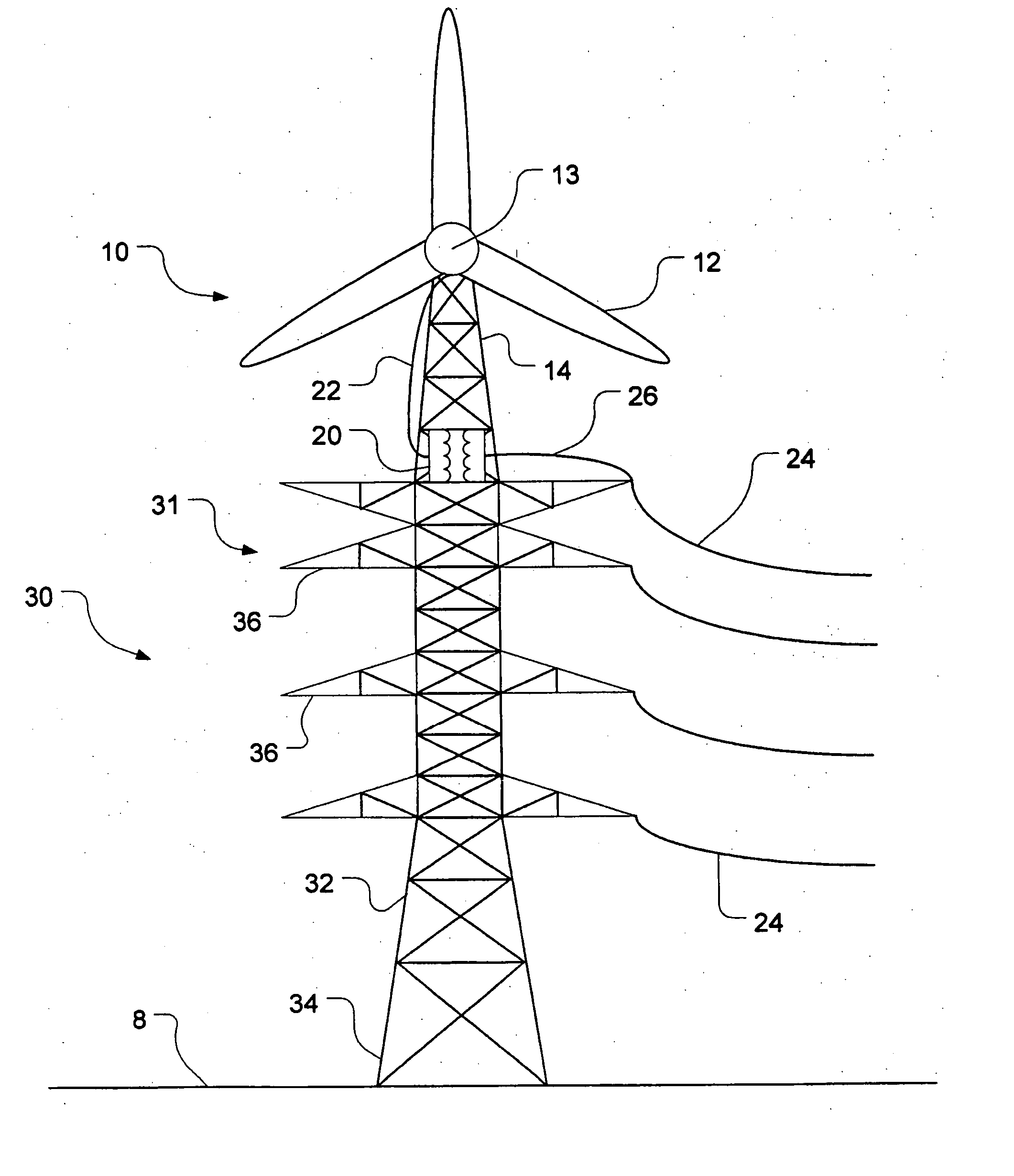
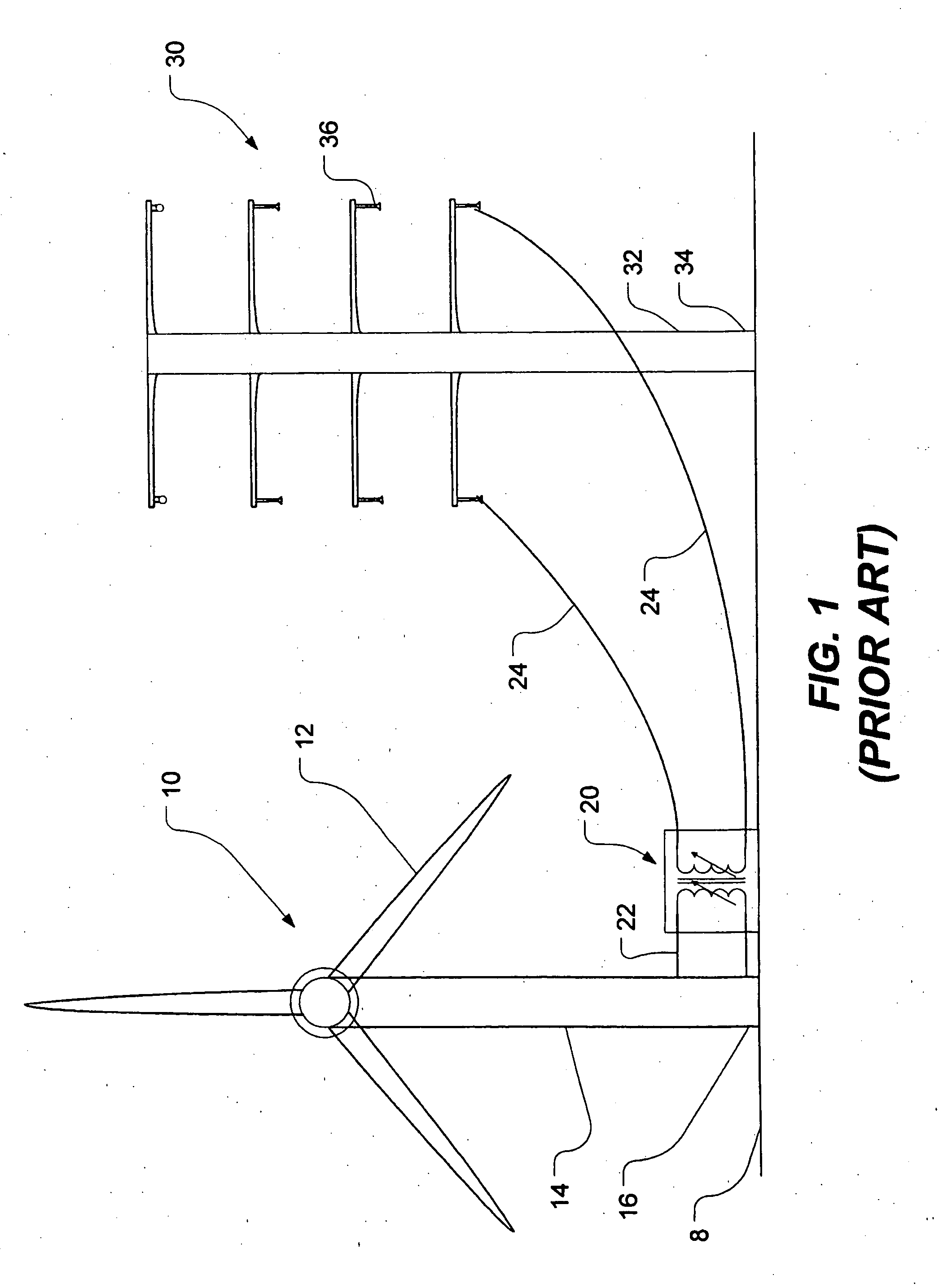
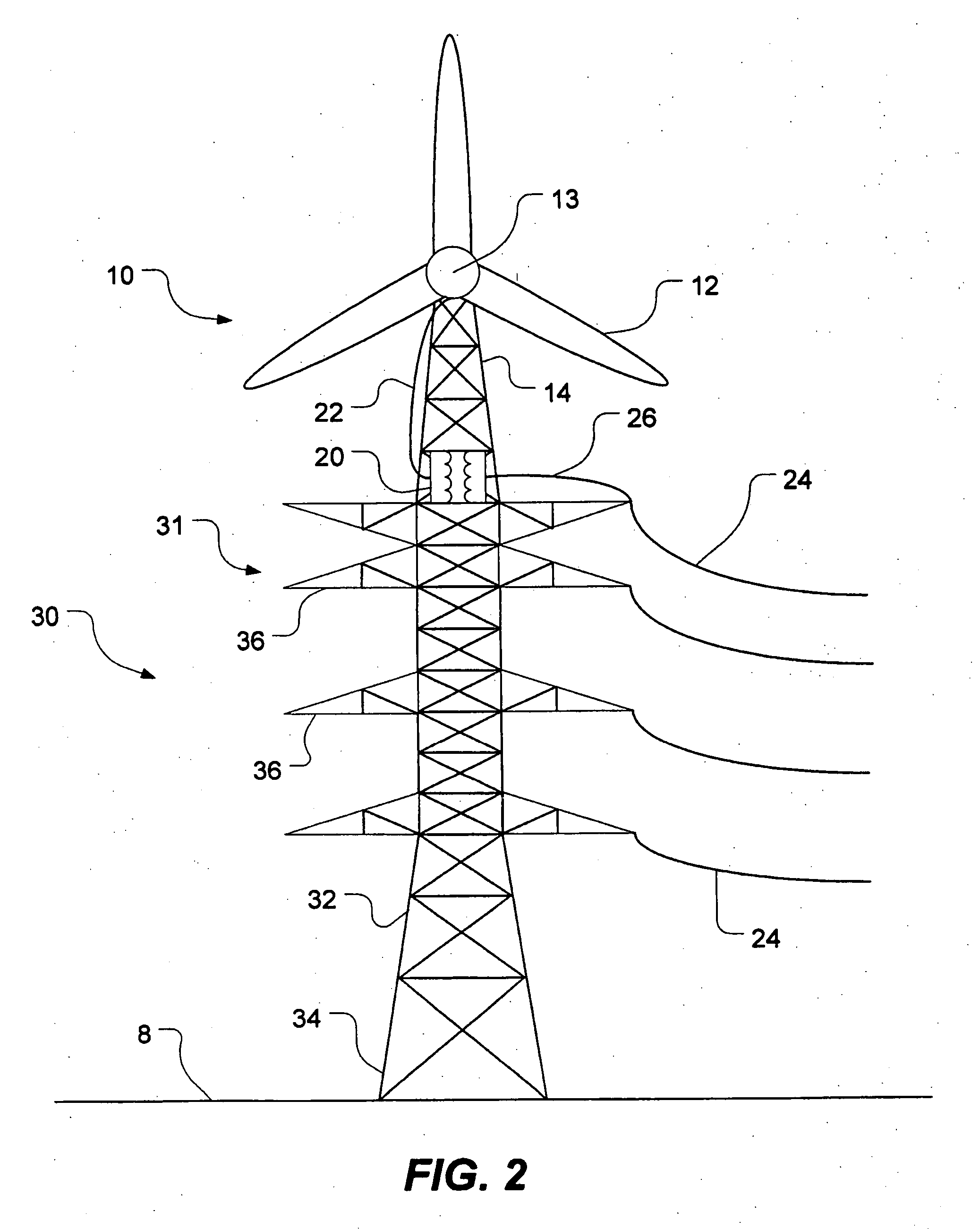
[0026]FIG. 2 shows a horizontal-axis wind turbine generally designated by reference numeral 10 mounted to a power transmission tower 30 in accordance with the present invention. For the purposes of this specification, the expression “power transmission tower” includes any transmission tower, distribution tower, tower, pole or other structure capable of carrying electric power lines above ground.

[0027] As shown in FIG. 2, the horizontal-axis wind turbine 10 has three rotor blades 12 for driving an electric generator, which is housed within a nacelle 13. The generator is preferably horizontal-axis as well although its orientation may conceivably differ depending on the connection between the rotor and the generator. For the purposes of this specification, the expression “generator” means a generator, alternator or any other electricity-producing device capable of converting the kinetic energy of a rotor into electricity.

[0028] of course, the wind turbine may have a different number o...

second embodiment

[0031]FIG. 3 shows the present invention in which a horizontal-axis wind turbine 10 is mounted atop a monopole power transmission tower 30. The tower structure 32 of the monopole tower is typically tapered. The base 34 of the tower is anchored to the ground 8. The tower has a plurality of supporting arms 36 for suspending power lines. Connected to the top of the tower 30 is the wind turbine 10. The wind turbine is supported above the power lines by a substructure or tower extension 14 which, in this case is monopole although it could be lattice or hybrid. The transformer 20 is mounted either to the wind turbine or to the power transmission tower 30. Electric lines feed power that is generated by the wind turbine into the power lines 24. The wind turbine is shown to be a horizontal-axis wind turbine. This horizontal-axis wind turbine may be mounted anywhere on the power transmission tower provided it does not interfere with the power lines. However, the horizontal-axis wind turbine i...

third embodiment

[0032]FIG. 4 depicts the present invention in which a wind turbine 10 is mounted atop a power transmission tower 30 having a hybrid tower structure 32. Such towers are known as “hybrid” because they are a combination of lattice and monopole structures. In this case, the hybrid tower has three support legs, as shown. Mounted atop the hybrid power transmission tower 30 is a lattice substructure or tower extension 14 which supports a wind turbine 10. The substructure 14 could also be monopole or hybrid. The wind turbine 10 has a horizontal-axis generator housed within the nacelle 13. A transformer 20, mounted either to the tower extension 14 or to the power transmission tower 30, steps up the voltage being output from the wind turbine before being fed into the power lines carried by the supporting arms 36 of the power transmission tower 30.


PUM


Abstract

A power transmission tower carrying power lines has a wind turbine mounted to an upper portion of the tower. The wind turbine has a rotor which drives a generator for generating electric power. The generated power is stepped up using a transformer before being fed into one of the power lines. Optionally, electric power generated by a plurality of such wind turbines could be accumulated downstream and then transformed and fed into the grid at multiple-tower intervals. The wind turbine can be mounted on a lattice tower, a monopole tower or a hybrid tower. The wind turbine has either a fixed horizontal axis or a variable (but non-vertical) axis. Alternatively, a vertical-axis wind turbine may be used provided the generator is mounted at or near the top of the tower. Using existing infrastructure, the present invention supplements the capacity of a power grid with environmentally friendly power generation.

Description

CROSS-REFERENCE TO RELATED APPLICATIONS [0001] This application claims the benefit of priority under 35 U.S.C. §119 from Canadian Patent Application serial number as yet unknown which was filed on Mar. 26, 2004 listing Andre Brunet as the inventor. TECHNICAL FIELD [0002] The present invention relates generally to electric power generation and, in particular, to a wind turbine for a power transmission tower. BACKGROUND OF THE INVENTION [0003] Wind turbines provide a clean and “environmentally friendly” alternative to generating electric power with coal-fired and nuclear plants. Wind turbines use rotor blades to harness wind power by converting the kinetic energy of the wind into rotational energy of a generator which in turn converts the rotational energy into electric power in a manner well known in the art. [0004] The power extracted from the wind is proportional to the cube of the wind speed and therefore wind turbines are most effective where the average wind speed is high. In or...

Claims


Application Information

Patent Timeline
Patent Type & Authority Applications(United States)
IPC IPC(8): F03B7/00F03D1/00F03D9/00H02P9/04
CPCF03D1/00F03D9/003Y02E10/728Y02B10/30F05B2240/9121F03D9/255Y02E10/72F03D13/20
Inventor BRUNET, ANDRE
Owner BRUNET ANDRE
Why Eureka
Try Eureka