Current driver employing pulse-width modulation

a pulse-width modulation and current driver technology, applied in the direction of field or armature current control, position/direction control, electric variable regulation, etc., can solve the problem of introducing error or delay into the output pwm signal, using such a low-pass filter, and measuring average current which fluctuates over tim

Inactive Publication Date: 2005-10-20
LYNCH FLUID CONTROLS
View PDF6 Cites 13 Cited by
  • Summary
  • Abstract
  • Description
  • Claims
  • Application Information

AI Technical Summary

Problems solved by technology

Disadvantageously, and as will be described later in greater detail, both the manner in which the average current is determined and the manner in which the measured average current is compared to the input value may introduce error or delay into the output PWM signal.
Two problems may result from the use of such a low-pass filter.
First, the output of the low pass filter can still have an AC component, resulting in a measured average current which fluctuates over time.
The measured average current may therefore be erroneous depending upon the exact moment in time at which the value is sampled.
Secondly, because the RC circuit introduces lag, a delay will exist between any input adjustments and a resultant change in the output PWM signal.
This component also disadvantageously introduces a delay between any input adjustments and resultant output PWM signal changes.

Method used


Image

  • Current driver employing pulse-width modulation
  • Current driver employing pulse-width modulation
  • Current driver employing pulse-width modulation

Examples


Embodiment Construction

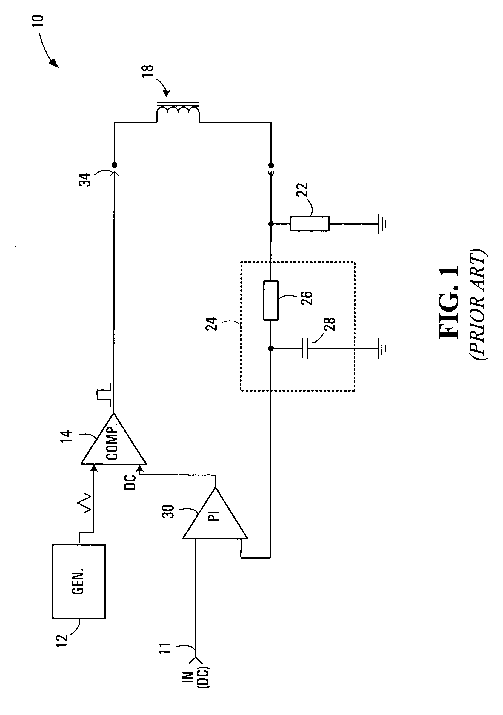
[0021]FIG. 1 illustrates a known closed-loop control system 10 for generating a pulse-width modulation signal. The control system 10 has an input 11 and an output 34. The input 11 is for connection to a DC voltage which represents a desired average output current setting. The output 34 provides a generated PWM signal for driving an external electronic device, such as a solenoid 18, which signal has an average current that is proportional to the input DC voltage.

[0022] Control system 10 includes a triangular waveform generator 12 and a comparator 14. These two components are used to generate the output PWM signal. More specifically, the output of the triangular waveform generator 12 serves as one input to the comparator 14. The other input to the comparator 14 is a signal representative of error between desired output current (i.e. the voltage applied to input 11) and measured output current. The error value is a DC voltage whose level is between the maximum and minimum voltage of t...


PUM


Abstract

A current driver capable of generating a controlled current in the form of a pulse-width modulation (PWM) signal suitable for controlling an electronic device such as a solenoid is disclosed. The current driver has a feedback loop incorporating a dual-slope integrator. During an integration phase, which has a duration of one or more PWM periods, the dual-slope integrator integrates a signal indicative of the current flowing through the device. During a de-integration phase, the time required for the integrated signal to discharge at a known rate is measured. The measured time and integration phase duration are used to determine average output current. Any error between the measured and desired average output current is corrected by way of a multiplicative corrective factor or an additive corrective factor. The integration and de-integration phases may occur during alternating PWM periods.

Description

FIELD OF THE INVENTION [0001] The present invention relates to a current driver which provides a controlled current suitable for controlling an electronic device such as a solenoid. More particularly the present invention relates to current driver which provides a controlled current in the form of a pulse-width modulation (PWM) signal. BACKGROUND OF THE INVENTION [0002] Control systems capable of generating an electronic pulse-width modulation signal for controlling electronic devices are well known. Such systems are commonly employed to control solenoids which are used to open and close valves in hydraulic systems. [0003] When an electronic device is controlled through PWM, correction of the output PWM signal may be necessary, either due to fluctuations in power supply voltage or due to fluctuations in the inductance and resistance of the electronic device resulting from changes in temperature and valve spool position. This correction is commonly achieved through feedback control o...

Claims


Application Information

Patent Timeline
Patent Type & Authority Applications(United States)
IPC IPC(8): H02M1/12H02M3/156
CPCH02M3/156H02M2003/1555H02M2001/0009H02M1/0009H02M3/1555
Inventor SMARANDACHE, SANDU MARGARIT
Owner LYNCH FLUID CONTROLS
Why Eureka
Try Eureka