In-frame repair of gas turbine components

a gas turbine and in-frame technology, applied in the field of in-frame repair of gas turbine components, can solve the problems of oxidation of the substrate, localized loss, or spallation of the ceramic layer, damage to the coating during service operation,

Inactive Publication Date: 2005-10-27
SIEMENS ENERGY INC
View PDF55 Cites 119 Cited by
  • Summary
  • Abstract
  • Description
  • Claims
  • Application Information

AI Technical Summary

Problems solved by technology

Although these coatings have been designed to have a service life of several thousand hours, the coatings may be damaged during their service operation.
For example, localized loss, or spallation, of the ceramic layer may occur as a result of foreign-object-damage (F.O.D.) or

Method used


Image

  • In-frame repair of gas turbine components
  • In-frame repair of gas turbine components
  • In-frame repair of gas turbine components

Examples


Embodiment Construction

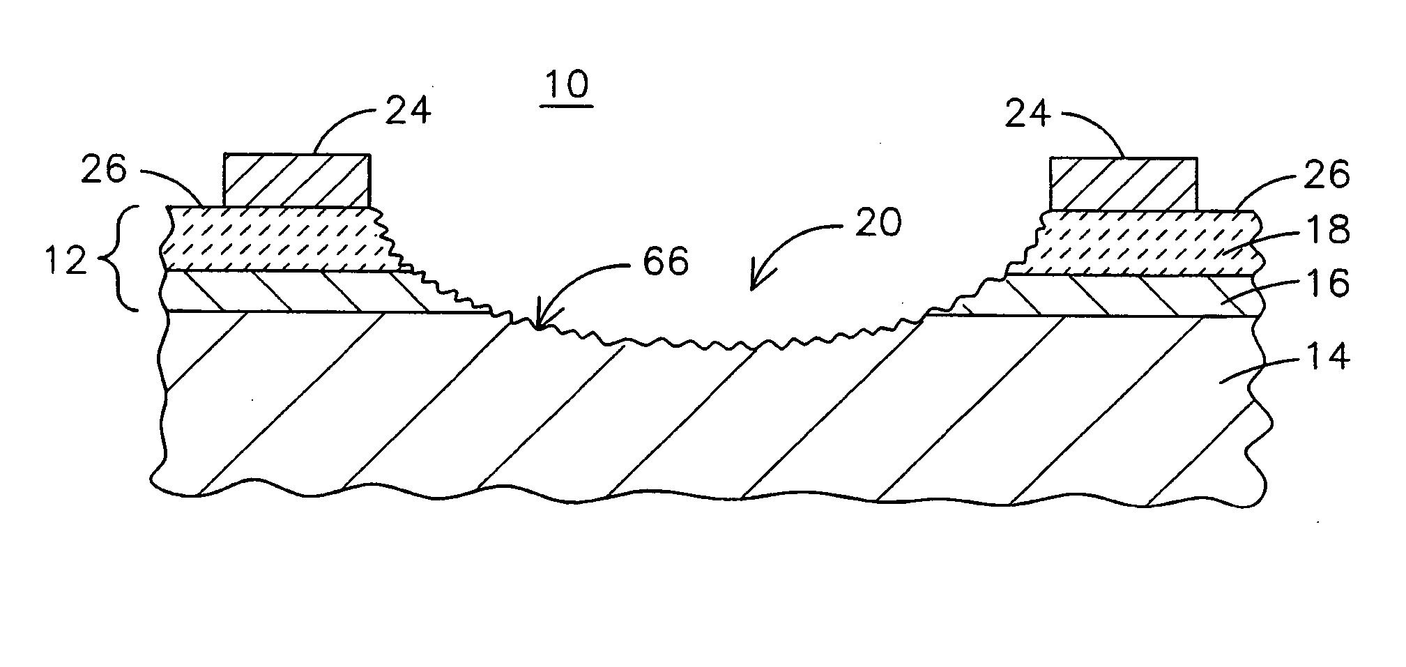
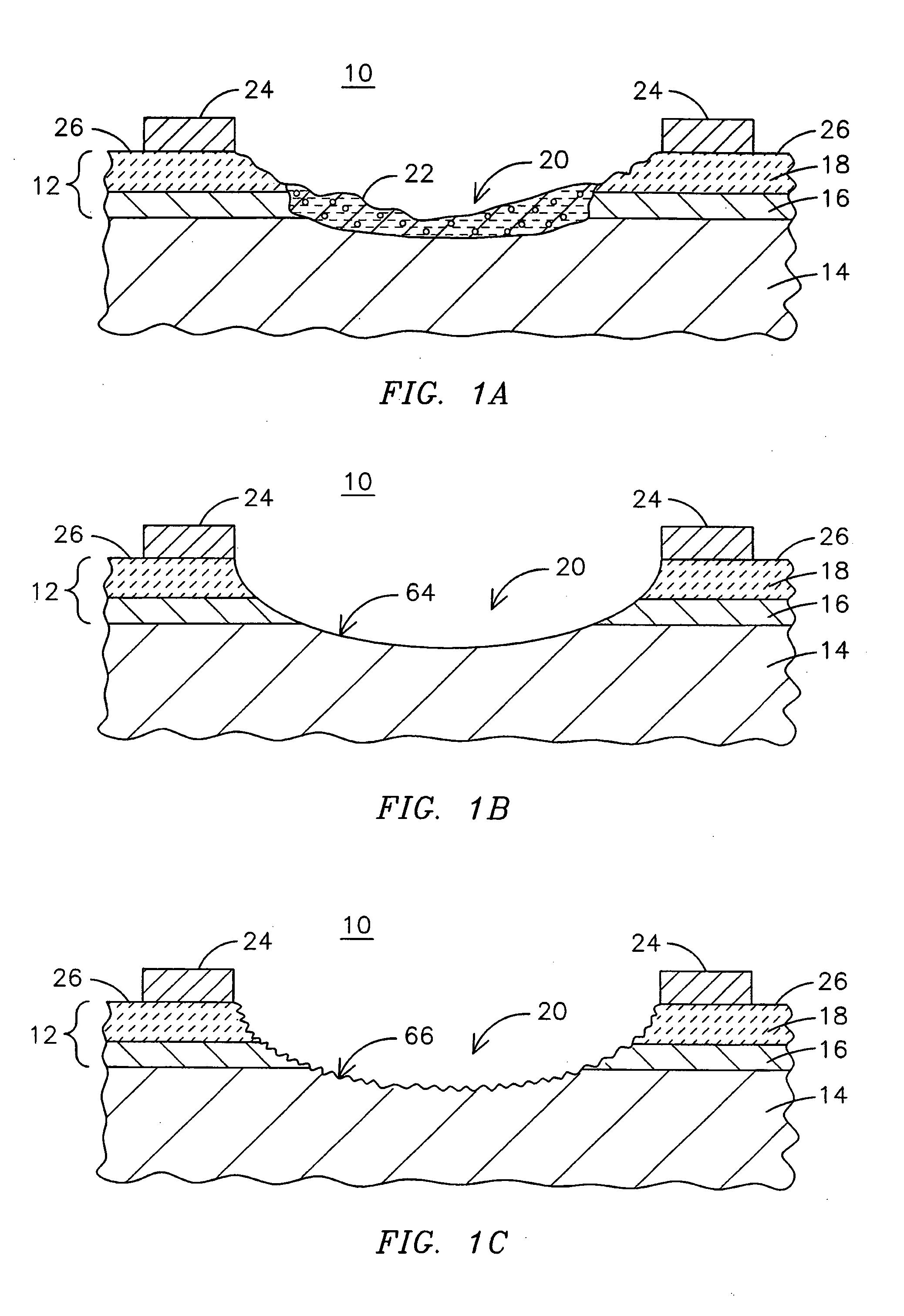
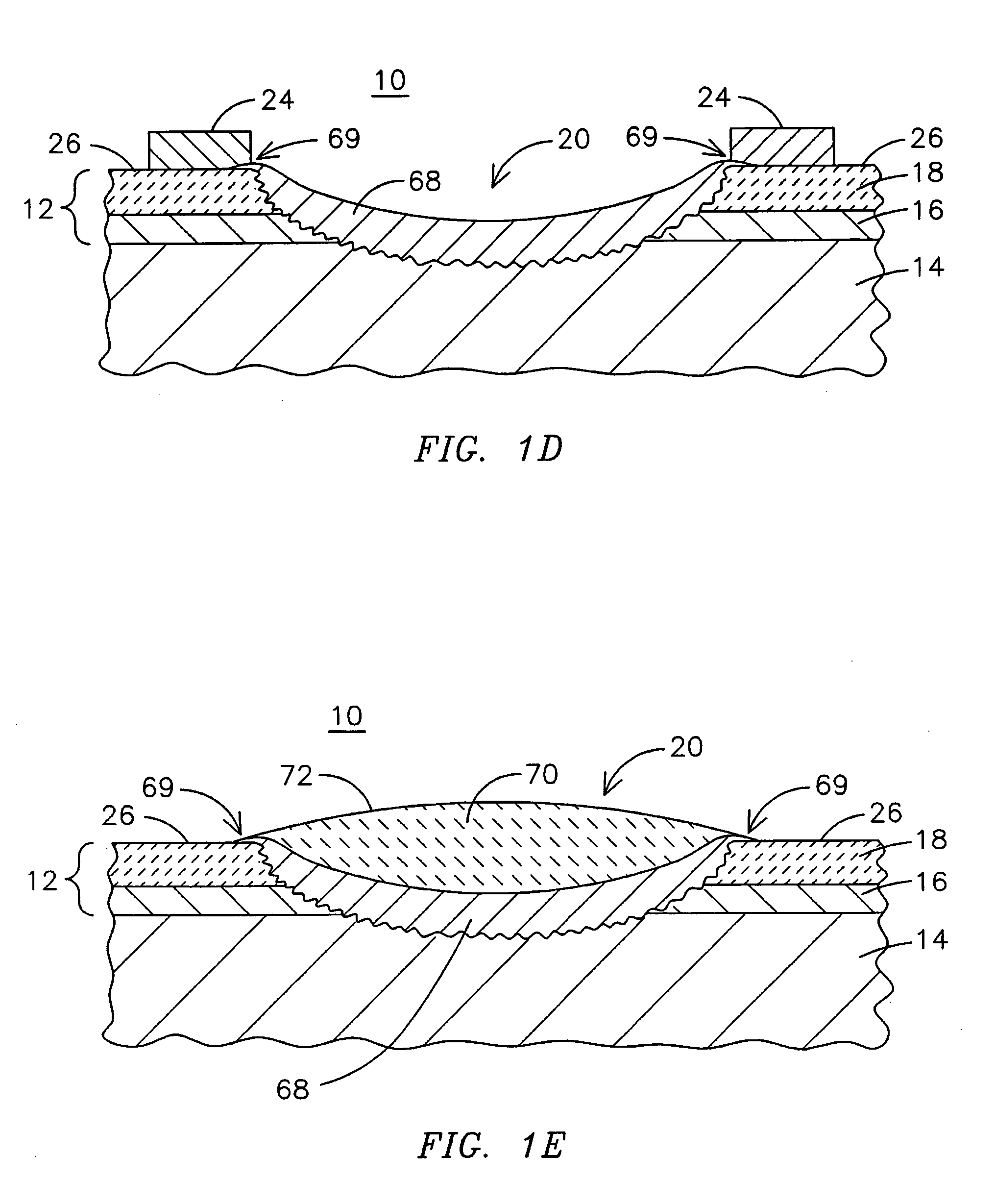
[0006] Conventional methods of removal and repair of TBC coatings of gas turbine components may be prohibitively expensive and time consuming. In place, or in-frame, repair methods that do not require removal of a component to be repaired from the gas turbine have been proposed, but the longevity of such repairs may be limited. The present inventors have developed an innovative system and method of performing in-frame repair of TBCs of gas turbine components that may provide a service life of the repaired component comparable to, or at least a majority portion of a service life of a component re-coated within a shop-floor environment. In laboratory tests performed on components repaired using this innovative method, service lives for the repaired components have ranged from 8,000 to 24,000 service operation hours, a service life length that may not be achievable by other proposed in-frame methods. Unlike conventional techniques that require removal, repair, and later reinstallation ...


PUM

PropertyMeasurementUnit
Surface roughnessaaaaaaaaaa
Temperatureaaaaaaaaaa
Sizeaaaaaaaaaa

Abstract

A method for in-frame repairing of a thermal barrier coating (12) on a gas turbine component includes cleaning a desired surface portion (10) of the component without removing the component from the gas turbine. The method also includes roughening the surface portion in-frame, applying a bond coat (68) to the surface portion in-frame, and applying a ceramic topcoat (70) to the bond coat, in-frame. A system (28) for cleaning the surface portion in-frame includes an abrasive media (34) having a state change characteristic occurring at a temperature lower than an operating temperature of the gas turbine so that the abrasive media changes from a solid state to another state allowing the media to exit the gas turbine during operation. The system also includes an abrasive media sprayer (36) to direct a spray of the abrasive media at the desired surface portion.

Description

FIELD OF THE INVENTION [0001] This invention relates generally to in-frame repair of ceramic thermal barrier coatings on components in gas turbines. BACKGROUND OF THE INVENTION [0002] Ceramic thermal barrier coatings (TBC's) are well known for protecting superalloys or ceramic matrix composite material substrates from high temperature environments in a gas turbine. One type of thermal barrier coating used to protect a nickel-based or cobalt-based superalloy component includes an “MCrAlY” bond coat, where M is iron, nickel, cobalt or a combination thereof, that functions primarily as an intermediate bonding layer for the Ceramic Top Coat. A typical composition of this ceramic layer is Yttria Stabilized Zirconia (YSZ). The ceramic layer is typically deposited by air plasma spraying (APS), low pressure plasma spraying (LPPS), or by a physical vapor deposition (PVD) technique, such as electron beam physical vapor deposition (EBPVD) that yields a strain-tolerant columnar grain structure....

Claims


Application Information

Patent Timeline
IPC IPC(8): B21B1/00B23P6/00C23C4/02C23C28/00F01D5/28
CPCC23C4/02C23C28/3215C23C28/3455F01D5/288F05D2230/90Y10T29/49318C23C4/085C23C24/04Y10T29/49742Y10T29/53F05D2300/611C23C4/01C23C4/073
Inventor PHILIP, VINODSETH, BRIJZOMBO, PAULNAGLE, DENNIS
Owner SIEMENS ENERGY INC
Why Eureka
Try Eureka