
Dye-sensitized solar cell module

Inactive Publication Date: 2005-10-27
SAMSUNG SDI CO LTD
View PDF55 Cites 50 Cited by
  • Summary
  • Abstract
  • Description
  • Claims
  • Application Information

AI Technical Summary

Benefits of technology

[0012] In accordance with the present invention, a dye-sensitized solar cell module which involves simplified processing steps, and low production cost is provided.
[0013] Further in accordance with the present invention, a dye-sensitized solar cell module which involves enlarged active areas, and excellent photoelectric conversion efficiency without deteriorating the cell capacity due to the tape is also provided.

Problems solved by technology

However, such a dye-sensitized solar cell involves lower photoelectric conversion efficiency, and has limited practical use.
However, the above method involves complicated steps of processing the unit cells and rearranging them, and increased production cost.
Furthermore, the capacity of the dye-sensitized solar cell is deteriorated due to the conductivity of the conductive tape, and the active area of the module is reduced.

Method used


Image

  • Dye-sensitized solar cell module
  • Dye-sensitized solar cell module
  • Dye-sensitized solar cell module

Examples


second embodiment

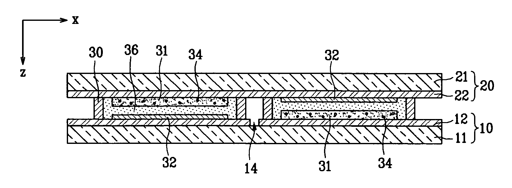
[0073]FIG. 4 is a partially exploded perspective view of the dye-sensitized solar cell module according to the present invention. A plurality of unit cells 40 are series-coupled to one another, as indicated by a dotted arrow 45, using insulation regions 42, 44 formed on the first or the second substrate 10, 20. That is, the insulation regions 42, 44 are formed on only one of the first or the second substrates 10, 20 between the unit cells 40 that are to be series-coupled, and the unit cells 40 are series-coupled to one another through the other substrate. In this embodiment, as parallel connection is not required, separate connectors are not required, and it is only necessary to receive the voltage at the two ends 47, 49 of the series-coupled unit cells 40.

third embodiment

[0074]FIG. 5 is a partial cross-sectional view of the dye-sensitized solar cell module according to the present invention.

[0075] In this embodiment, a separate reflective plate 46 is externally mounted to the first or the second substrate 10, 20. In one exemplary embodiment, the reflection plate 46 is placed opposite the entrance side of sunlight.

[0076] The reflective plate 46 may be formed with a metallic material, an oxide, a nitride, a carbonaceous compound or a polymer film, and the reflectivity thereof may be established to be in the range of 5-100%.

[0077] As shown in FIG. 5, in case the reflective plate 46 is installed external to the first substrate 10, the sunlight, incident upon the second substrate 20 and passing through the first substrate 10, is reflected by the reflective plate 46, and reenters the second substrate 20. Accordingly, as compared to the case where the reflective plate 46 is absent, a larger amount of sunlight can be absorbed, thereby enhancing the energy...


PUM


Abstract

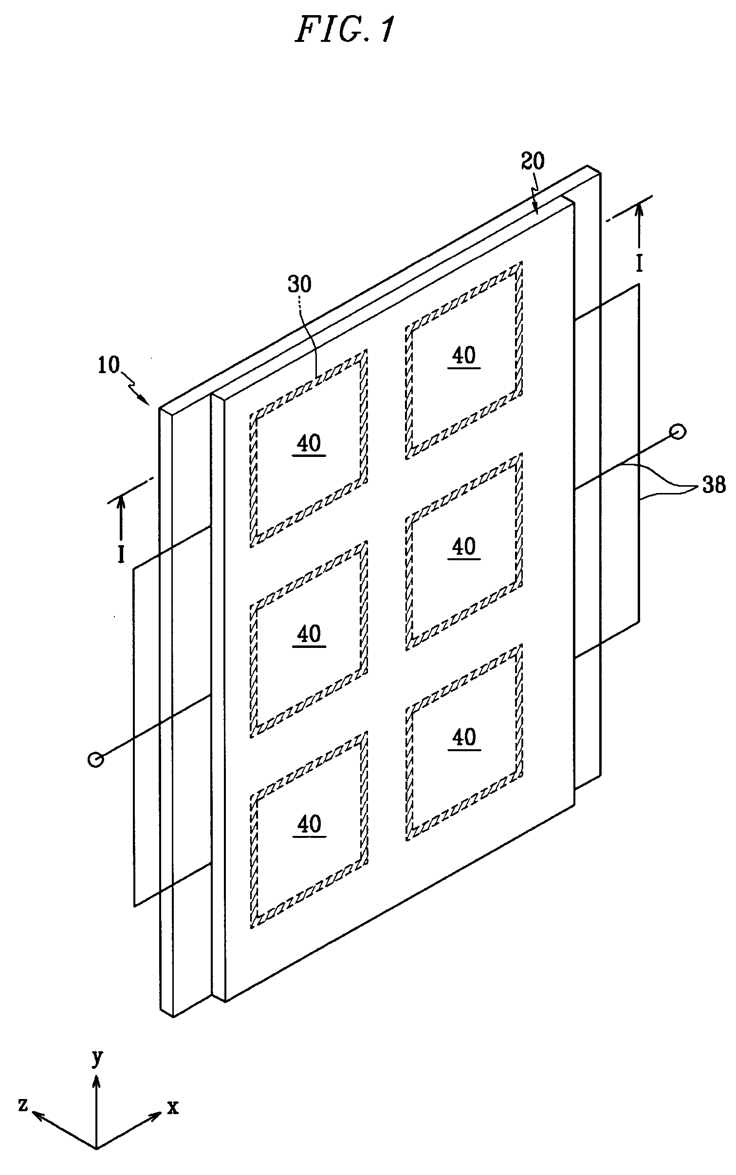
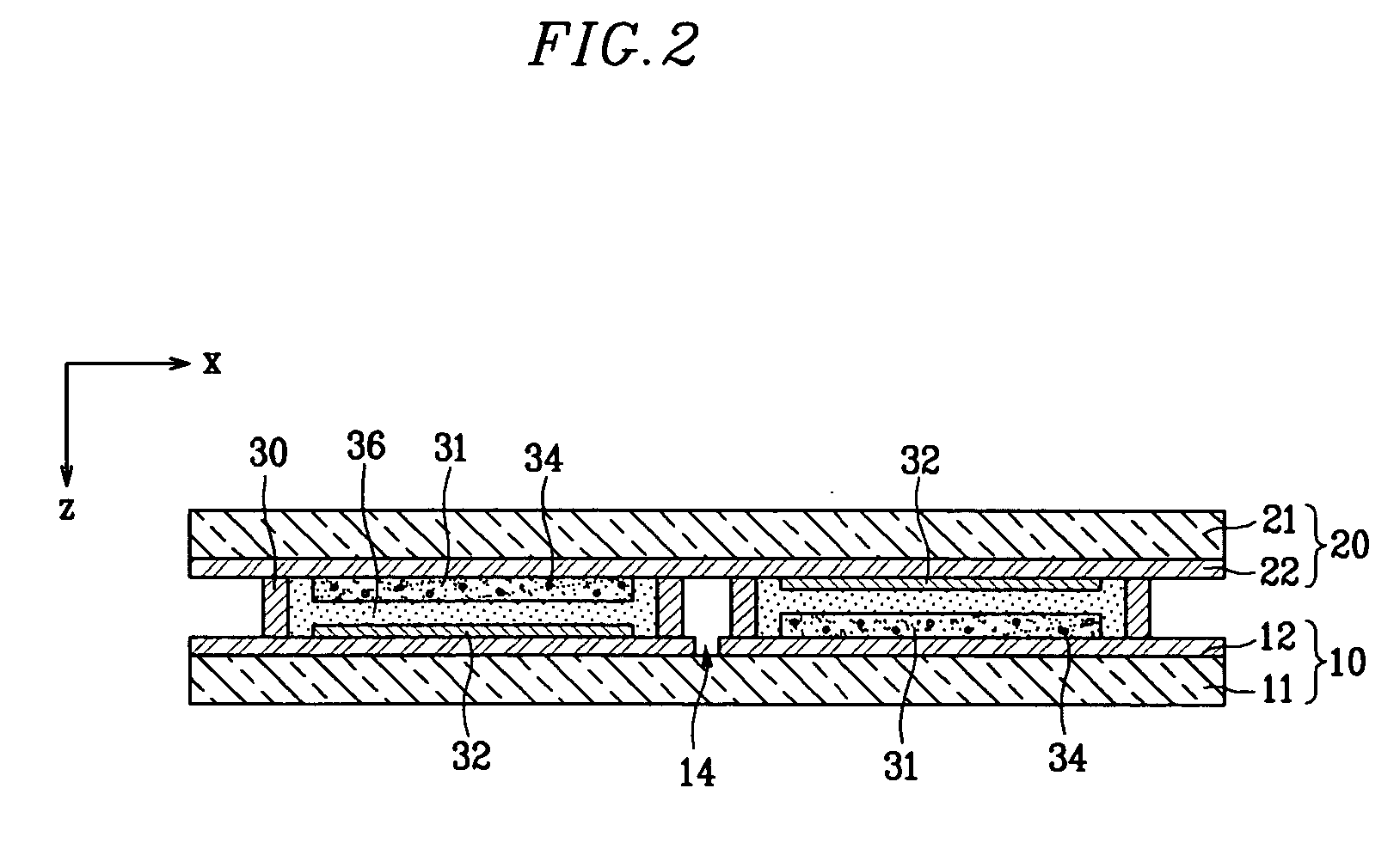
A high capacity dye-sensitized solar cell module where a plurality of unit cells are simultaneously formed at a substrate in a simplified manner with increased light absorption efficiency. The dye-sensitized solar cell module includes first and second conductive substrates facing one another with regions for a plurality of unit cells. First and second electrodes are formed on the first or the second substrate such that the first and the second electrodes face one another at the respective unit cells. A dye is adsorbed at the first electrode. The space between the first and the second substrates at the respective unit cells is filled with an electrolyte. Insulation regions are formed on at least one of the first and the second substrates between a pair of unit cells neighboring to one another. The pattern of insulation regions, on one or both of the substrates, results in the unit cells being coupled in series, in parallel, or in a combination manner.

Description

CROSS REFERENCE TO RELATED APPLICATION [0001] This application claims priority to and the benefit of Korean Patent Application No. 10-2004-0028155 filed on Apr. 23, 2004 in the Korean Intellectual Property Office, the entire content of which is incorporated herein by reference. BACKGROUND OF THE INVENTION [0002] 1. Field of the Invention [0003] The present invention relates to dye-sensitized solar cell modules, and in particular, to a dye-sensitized solar cell module which has a simple structure, and involves simplified processing steps and enhanced capacity. [0004] 2. Description of Related Art [0005] Generally, the dye-sensitized solar cell module has a first substrate with a first electrode based on a dye-adsorbed metallic oxide, and a second substrate with a second electrode spaced apart from the first substrate while facing it. An electrolyte is injected between the first and the second substrates. [0006] According to the basic principles of the dye-sensitized solar cells, when...

Claims


Application Information

Patent Timeline
IPC IPC(8): H01L31/04H01G9/20H01L31/00H01L31/042H01M14/00
CPCH01G9/2031Y02E10/542H01G9/2081H01G9/2059Y02P70/50H01L31/0224H01L31/042H01L31/18
Inventor AHN, KWANG-SOONLEE, JI-WONLEE, WHA-SUPCHOI, JAE-MANSHIN, BYONG-CHEOLPARK, JOUNG-WON
Owner SAMSUNG SDI CO LTD
Learn More