Method for manufacturing liquid crystal display device

Active Publication Date: 2005-12-20
LG DISPLAY CO LTD
View PDF6 Cites 1 Cited by
  • Summary
  • Abstract
  • Description
  • Claims
  • Application Information

AI Technical Summary

Benefits of technology

[0033]An advantage of the present invention is to provide to a method for manufacturing an LCD device having a reflective electrode with protrusions using simplified manufacturing process steps, thereby improving reflectivity.
[0034]Additional features and advantages of the invention will be set forth in the description which follows, and in part will become apparent from the description or may be learned from practice of the invention. The objectives and other advantages of the invention may be realized and attained by the structure particularly pointed out in the written description and claims hereof as well as the appended drawings.
[0035]To achieve these and other advantages and in accordance with the purpose of the invention, as embodied and broadly described, a method for manufacturing an LCD device includes The method includes: forming a first insulating layer on a substrate; forming a photoresist layer on the first insulating layer, wherein the photoresist layer has a plurality of rounded protrusions and rounded valleys; forming a plurality of rounded protrusions and rounded valleys on the first insulating layer by etching the first insulating layer and the photoresist layer; and forming a reflective electrode on the first insulating layer. The first insulating layer may be formed of an organic insulating layer such as acrylic resin, polyimide, BCB, oxide or nitride. Also, the etching process may be performed on the entire surface of the substrate with compound gas of SF6, O2 and He. The step of forming the photoresist layer may include: depositing a photoresist on the first insulating layer; performing a soft bake process on the substrate on which the photo

Problems solved by technology

Despite various technical developments in LCD technology with applications in different fields, research in enhancing the picture quality of the LCD device has been in some respects lacking as compared to other features and advantages of the LCD device.
However, the transmitting type LCD device has problems in that it has high power consumption.
However, the reflective

Method used


Image

  • Method for manufacturing liquid crystal display device
  • Method for manufacturing liquid crystal display device
  • Method for manufacturing liquid crystal display device

Examples


Example

[0051]Hereinafter, a method for manufacturing an LCD device according to the first embodiment of the present invention will be described with reference to the accompanying drawings.

[0052]FIG. 7A to FIG. 7F are cross-sectional views illustrating the manufacturing process steps of an LCD device according to the first embodiment of the present invention.

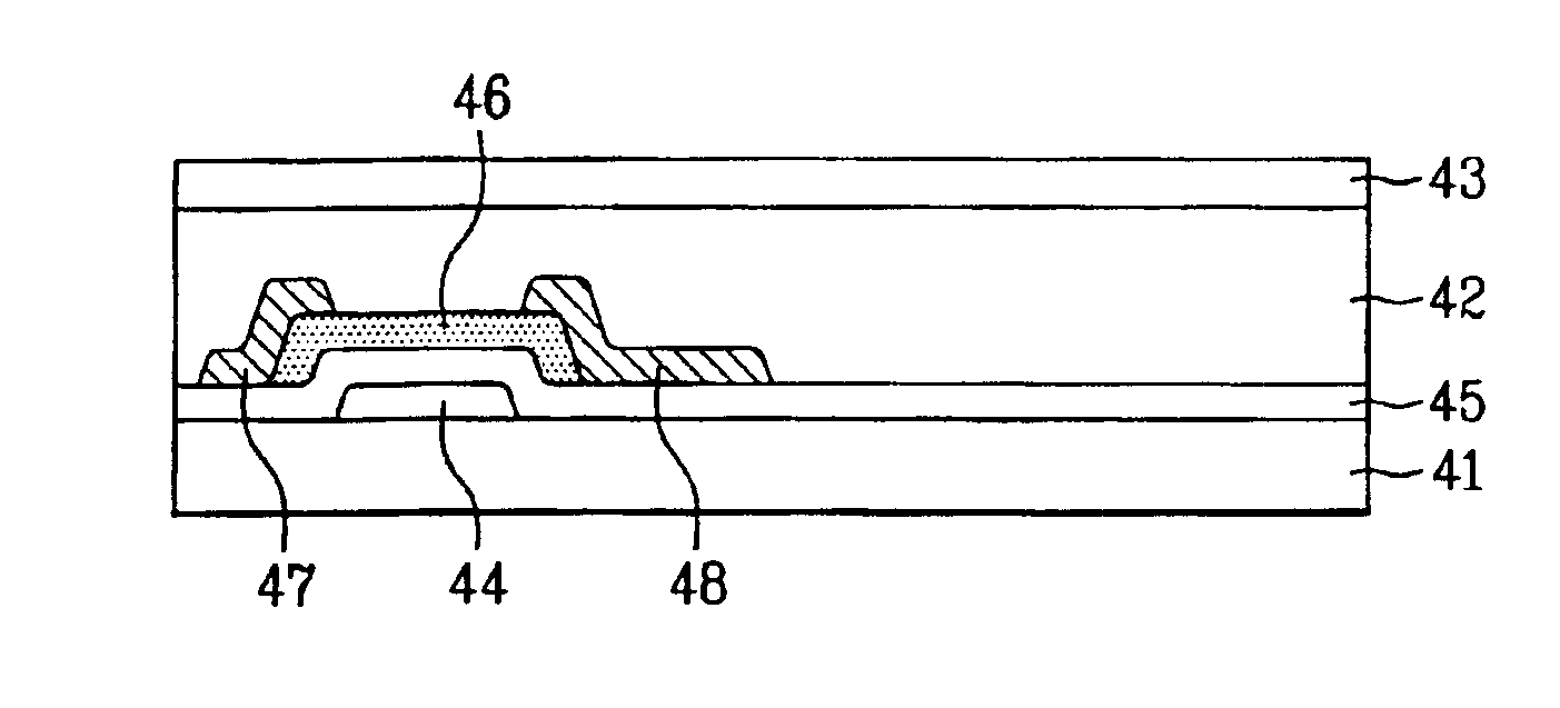
[0053]In FIG. 7A, a first insulating layer 42 is formed on an entire surface of a lower substrate 41 including a thin film transistor. The first insulating layer 42 may be formed of an organic insulating layer such as acrylic resin, polyimide, BenzoCycloButene (BCB), oxide layer, or nitride layer at a thickness between about 1 μm and about 5 μm. Next, a photoresist layer 43 is deposited on the first insulating layer 42. Then, a soft bake process may be performed on the lower substrate 41 to volatilize an organic solvent from the photoresist 43 deposited on the entire surface of the lower substrate 41 at a low temperature of about 80□ fo...


PUM


Abstract

A method for manufacturing an LCD device is disclosed, which has a reflective electrode having protrusions formed by simplified manufacturing process steps, thereby improving reflectivity. The method includes: forming a first insulating layer on a substrate; forming a photoresist layer on the first insulating layer, wherein the photoresist layer has a plurality of rounded protrusions and rounded valleys; forming a plurality of rounded protrusions and rounded valleys on the first insulating layer by etching the first insulating layer and the photoresist layer; and forming a reflective electrode on the first insulating layer.

Description

[0001]This application claims the benefit of the Korean Application No. P2002-44657 filed on Jul. 29, 2002, which is hereby incorporated by reference for all purposes as if fully set forth herein.BACKGROUND OF THE INVENTION[0002]1. Field of the Invention[0003]The present invention relates to a method for manufacturing a liquid crystal display (LCD) device, and more particularly, to a method for manufacturing an LCD device for improving reflectivity.[0004]2. Discussion of the Related Art[0005]With development of the information society, the demand for various display devices increases. Accordingly, many efforts have been made in researching and developing various flat display devices such as the liquid crystal display (LCD), the plasma display panel (PDP), the electro luminescent display (ELD), and the vacuum fluorescent display (VFD), and some species of these flat display devices are already applied to displays of various equipment.[0006]Among the various flat display devices, the ...

Claims


Application Information

Patent Timeline
IPC IPC(8): G02F1/1335G02F1/1343G02F1/1362G02F1/1368G06F1/10G02F1/1333H03K5/00H04L7/00
CPCG02F1/13439G06F1/10G02F2203/02G02F1/136227G02F1/1335
Inventor RYU, HEE YEONG
Owner LG DISPLAY CO LTD
Why Eureka
Try Eureka