Transparent laminate, pen-input image display, and image display method

a pen-input image display and transparent laminate technology, applied in static indicating devices, instruments, synthetic resin layered products, etc., can solve the problems of reducing the weight, size and thickness of the conventional pen-input image display device, causing image blurring, and so small tool force, so as to reduce the weight, size and thickness of the required device, and prevent image blurring caused by reflection. , the effect of eliminating parallax

Inactive Publication Date: 2005-10-27
NITTO DENKO CORP
View PDF6 Cites 45 Cited by
  • Summary
  • Abstract
  • Description
  • Claims
  • Application Information

AI Technical Summary

Benefits of technology

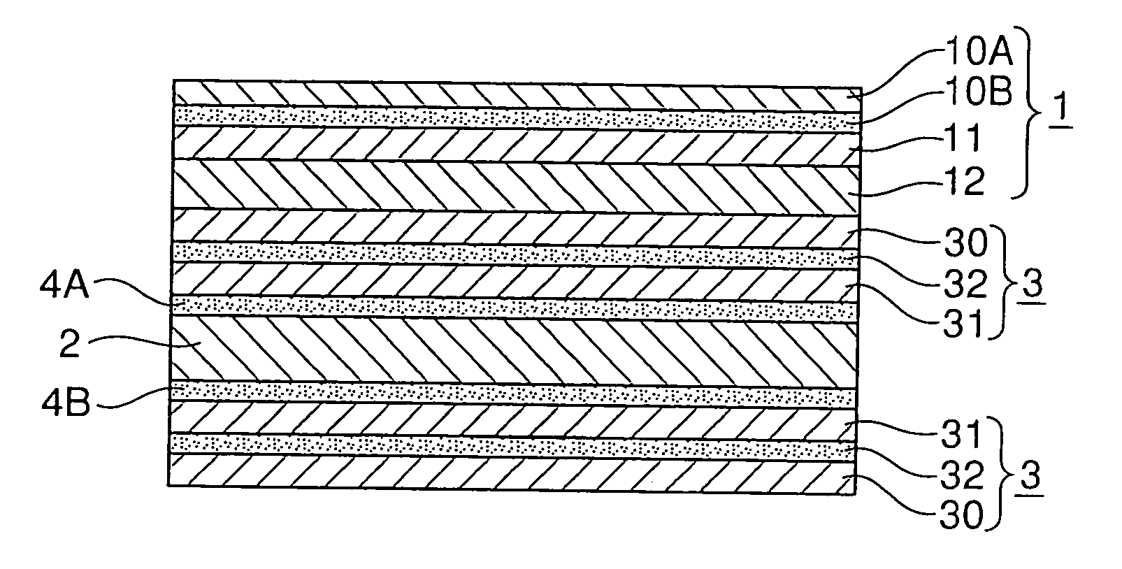
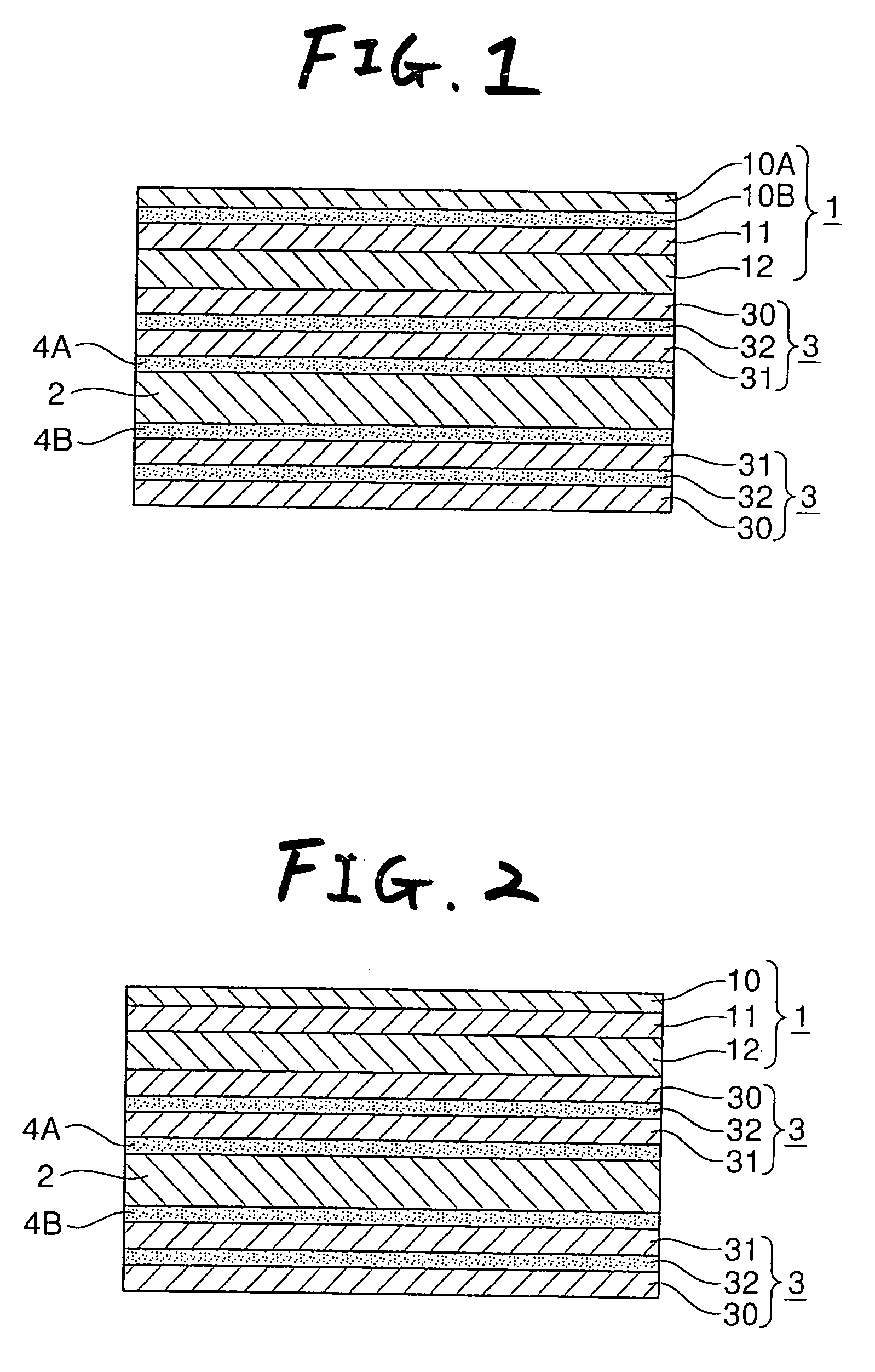
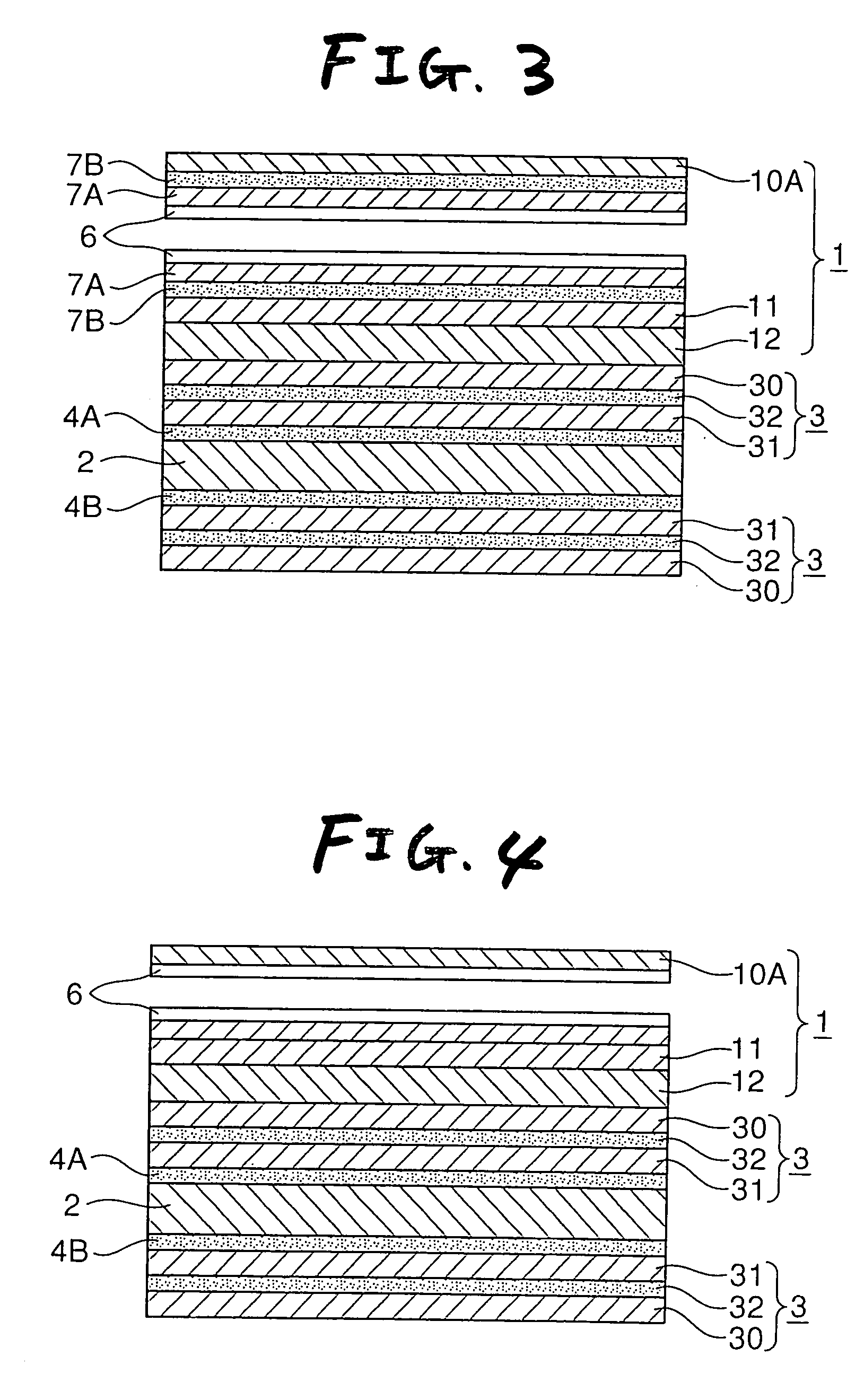
[0012] As described above, in accordance with the invention, a surface-treated layer, a transparent rigid layer and a transparent relaxing layer are laminated in this order to form a transparent laminate. The transparent laminate is directly laminated onto a visual surface side of an image display panel through a suitable optical film or the like. Accordingly, because the gap of an air layer in a conventional protective sheet can be eliminated, parallax is eliminated. Image blurring caused by reflection can be prevented. Moreover, because there is no protective sheet, reduction in weight, size and thickness can be attained. The invention is so simple in configuration that reduction in cost can be attained. Moreover, image smearing due to pen-input can be reduced as a function. Moreover, while the feeling of writing can be kept good, the crack of the image display panel due to external impact can be prevented. In this manner, various effects can be provided.

Problems solved by technology

It is however difficult in the conventional pen-input image display device to reduce the weight, size and thickness which is required in view of portability of the device since the protective sheet is formed.
Moreover, image blurring is caused by a parallax and a reflection reducing process since there is the gap of the air layer.
In addition, the tool force is so small that the feeling of drawing the pen becomes poor since a hard sheet such as an acrylic sheet is used as the protective sheet.
On the other hand, in a configuration in which an anti-reflection layer (or an anti-mirroring layer) or a polarizing plate and a retardation plate as an optical layer is provided directly on the image display panel without provision of the protective sheet, there is a problem in image smearing caused by the pen input, bad feeling of writing and breaking of the image display panel caused by impact of external force.

Method used


Image

  • Transparent laminate, pen-input image display, and image display method
  • Transparent laminate, pen-input image display, and image display method
  • Transparent laminate, pen-input image display, and image display method

Examples


example 1

(1) Surface-Treated Film

[0128] A polyethylene terephthalate film (“NO5S” manufactured by Kimoto Ltd.) subjected to an antiglare hard coating treatment and having a thickness of 125 μm was used.

(2) Transparent Rigid Layer

[0129] 100 parts of 3,4-epoxycyclohexylmethyl-3,4-epoxycyclohexane carboxylate, 120 parts of methyl tetrahydrophthalic anhydride as a curing agent and 2 parts of tetra-n-butylphosphoniumO,O-diethylphosphodithioate as a curing accelerator were mixed while stirred. An epoxy resin film 600 μm thick was thermally cured at 180° C. for 30 minutes by a flow casting method. Thus, a transparent rigid layer was prepared. The dynamic storage modulus G′ of the transparent rigid layer at 20° C. was as shown in Table 1.

(3) Transparent Relaxing Layer

[0130] In a reactor having a cooling pipe, a nitrogen-import pipe, a thermometer, an ultraviolet irradiator and a stirrer, 100 parts of 2-ethylhexyl acrylate and 0.1 parts of 2,2-dimethoxy-2-phenylacetophenone (photopolymerizati...

example 2

[0139] A transparent laminate was prepared in the same manner as in Example 1 except that the thickness of the transparent relaxing layer was changed to 500 μm. The transparent laminate was used for producing an electromagnetic induction type pen-input liquid crystal display device in the same manner as in Example 1.

example 3

[0140] A transparent relaxing layer was prepared in the same manner as in Example 1 except that 100 parts of 2-ethylhexyl acrylate used for formation of the transparent relaxing layer were replaced by the same amount of butyl acrylate. The transparent relaxing layer was used for preparing a transparent laminate in the same manner as in Example 1. The transparent laminate was used for producing an electromagnetic induction type pen-input liquid crystal display device in the same manner as in Example 1.


PUM

PropertyMeasurementUnit
dynamic storage modulus Gaaaaaaaaaa
dynamic storage modulus G'aaaaaaaaaa

Abstract

A surface-treated film, a transparent rigid layer and a transparent relaxing layer are laminated in this order to form a transparent laminate. Particularly, the transparent relaxing layer is made of an adhesive. The dynamic storage modulus G′ of the transparent rigid layer at 20° C. is not lower than 2×10⁸ Pa. On the other hand, the dynamic storage modulus G′ of the transparent relaxing layer at 20° C. is not higher than 1×10⁷ Pa. The transparent laminate is directly laminated onto a visual surface side (pen-input side) of a liquid crystal panel provided as an image display panel so that the transparent relaxing layer is placed inward. Thus, a pen-input image display device is produced.

Description

FIELD OF THE INVENTION [0001] The present invention relates to a pen-input touch panel attached to a front surface of an FDP display device such as a liquid crystal display, and more particularly to a transparent laminate attached to a touch panel type pen-input image display device using an electromagnetic induction system or a resistive film system, and an image display method using the same. BACKGROUND ART [0002] Pen-input image display devices such as resistive film type or electromagnetic induction type pen-input liquid crystal displays have been already known and used publicly and known in patent documents (see JP 2001-243016 A). [0003] In a “tablet PC” known as this type display, as shown in FIG. 6, a hard coated film 41 having an anti-reflection layer (or an anti-mirroring layer) is laminated onto one or each of surfaces of a protective sheet 43 made of an acrylic sheet etc. through an adhesive layer 42, and the protective sheet 43 is attached onto a visual surface side (pen...

Claims


Application Information

Patent Timeline
Patent Type & Authority Applications(United States)
IPC IPC(8): B32B27/00G06F3/041G06F3/048
CPCG06F3/041G06F3/0488G06F3/0412G06F3/045G06F3/046G06F3/0393
Inventor HIEDA, YOSHIHIRONOGUCHI, TOMONORIKAWAMOTO, IKUOUMEHARA, TOSHIYUKIMIYATAKE, MINORU
Owner NITTO DENKO CORP
Why Eureka
Try Eureka