Light amplification element, light amplification apparatus and light amplification system

a technology of light amplification and light amplification element, which is applied in the direction of optics, laser details, instruments, etc., can solve the problems of low raman amplification efficiency, increased size of amplification apparatus, and high output excitation light source, so as to enhance the stimulation of raman scattering, improve amplification efficiency, and efficient excite plasmon

Inactive Publication Date: 2005-10-27
NEC CORP
View PDF13 Cites 44 Cited by
  • Summary
  • Abstract
  • Description
  • Claims
  • Application Information

AI Technical Summary

Benefits of technology

[0021] A second light amplification apparatus of the present invention is characterized by comprising a first or second light amplification element and refraction means. By irradiating excitation light onto the metal part through refraction means at a certain angle of incidence of plasmon absorption, it is possible to efficiently excite plasmon and further enhance stimulated Raman scattering in the Raman active section.

Problems solved by technology

111-117) has low Raman amplification efficiency, and therefore requires an optical fiber as long as several kilometers, which increases the size of the amplification apparatus.
For this reason, there is a problem that obtaining a sufficient amplification gain requires a high output excitation light source and also requires greater power c

Method used


Image

  • Light amplification element, light amplification apparatus and light amplification system
  • Light amplification element, light amplification apparatus and light amplification system
  • Light amplification element, light amplification apparatus and light amplification system

Examples


first embodiment

(Structure)

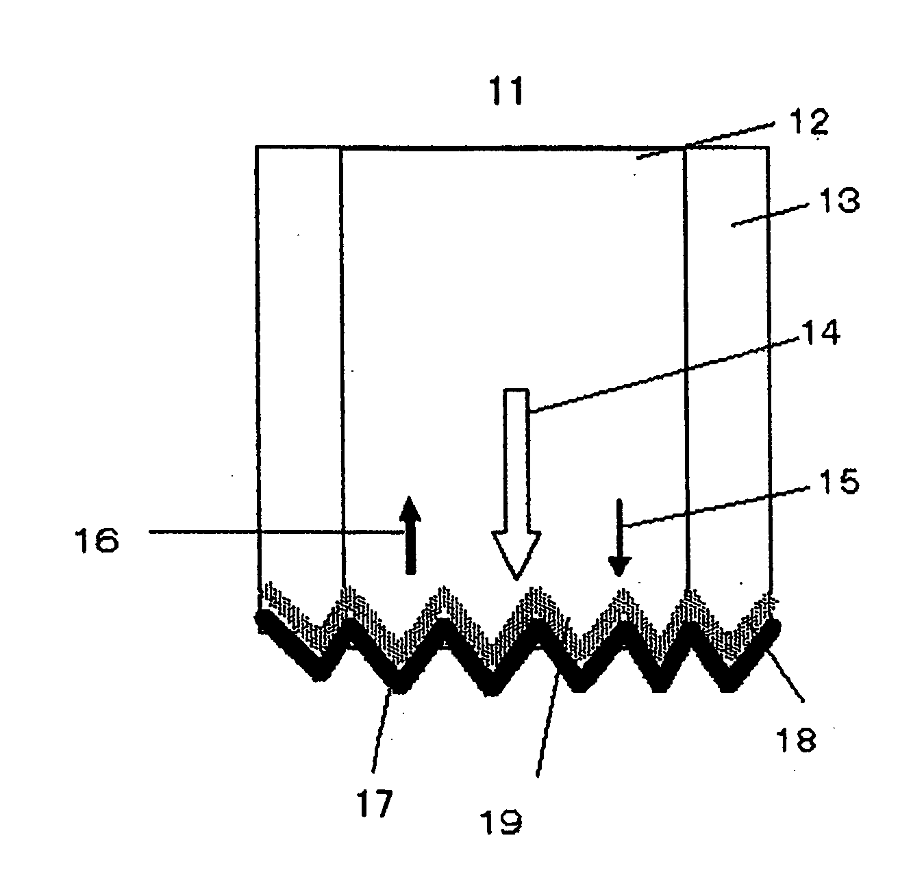
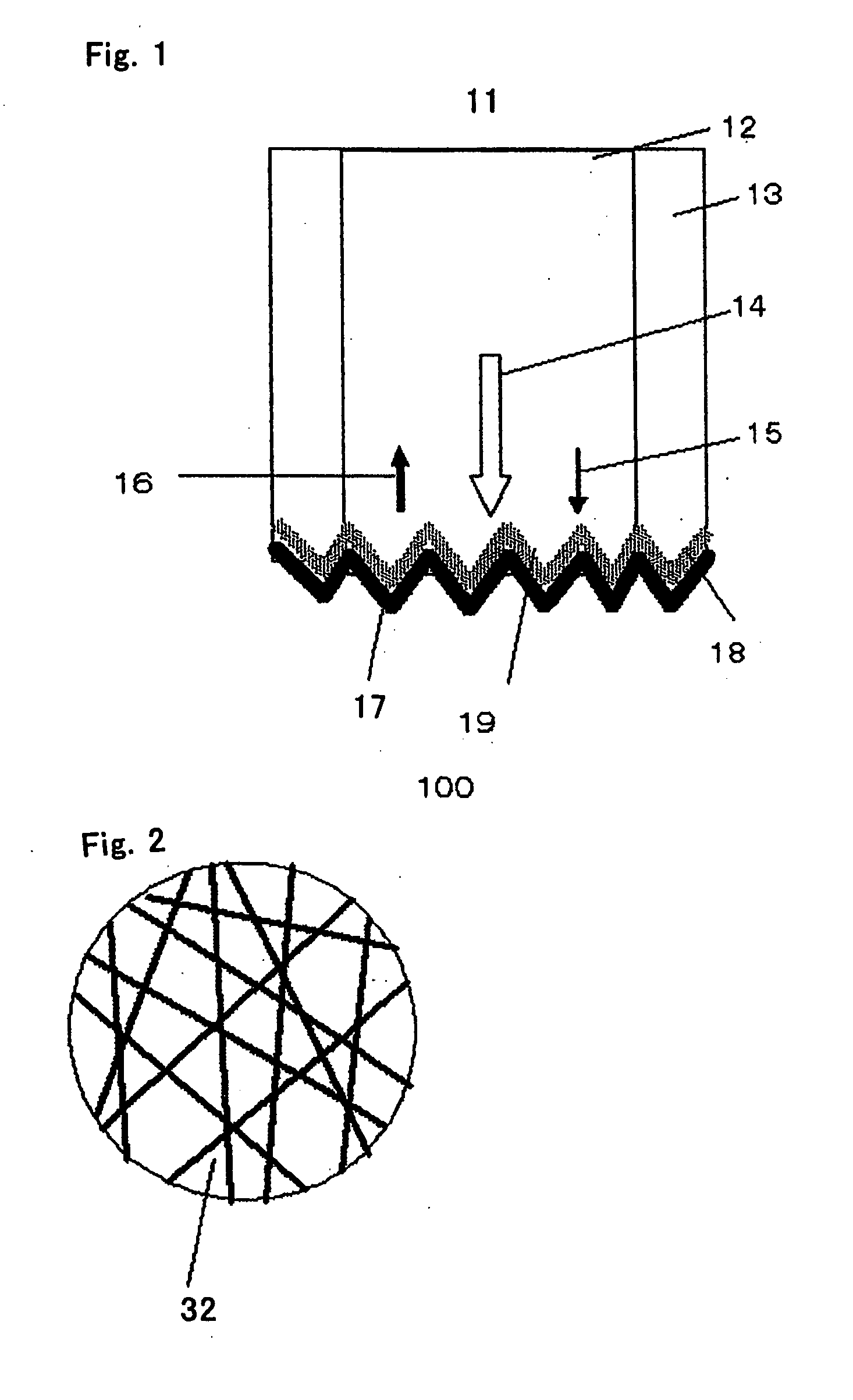
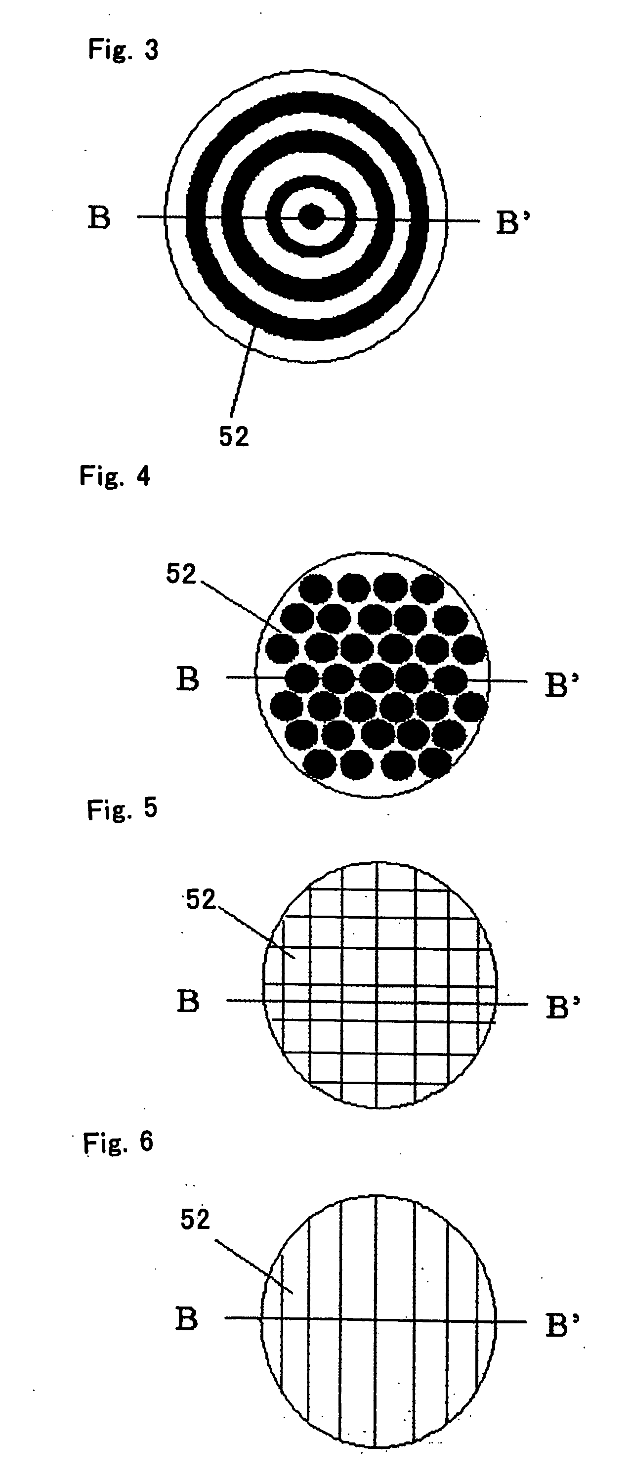
[0074]FIG. 1 shows the cross-sectional structure of a first embodiment of a light amplifier 100 of the present invention. According to FIG. 1, an end face 19 of an optical fiber 11 is made into a rough surface and a Raman active section 18 and metal part 17 are formed on the end face 19. Excitation light 14 and signal light 15 are irradiated onto the metal part 17 through the end face 19 and Raman active section 18. As shown in FIG. 2, the end face 19 is made up of an end face of random rough surface 32 having random roughness or an end face of periodic rough surface 52 having periodic roughness as shown in FIG. 3. Since the metal part 17 and Raman active section 18 are formed substantially following the shape of the end face 19, their surface and interface also have random or periodic roughness. The material of the Raman active section 18 will be explained later.

[0075] The roughness expressed here refers to a depth 34 which ranges from 1 nm to approximately a waveleng...

second embodiment

[0083] The cross-sectional structure of a light amplifier 110 according to a second embodiment of the present invention is shown in FIG. 11.

[0084] According to FIG. 11, a Raman active section 18 and a rough surface metal part 21 are formed on an end face of an optical fiber 11. The rough surface metal part 21 has a smooth surface 22 on the side contacting the optical fiber 11 and a rough surface 23 on the side facing the outside. Signal light 15 is irradiated onto the smooth surface 22 of the metal part and excitation light 14 is irradiated from the outside of the optical fiber onto the rough surface 23 of the rough surface metal part 21. What is different from the first embodiment lies in the excitation direction and the fact that one side of the rough surface metal part 21 is a smooth surface and the other side of the rough surface metal part 21 is a rough surface.

[0085] The rough surface 23 of the rough surface metal part 21 is shaped with random roughness as shown in FIG. 2 or...

third embodiment

[0089] The cross-sectional structure of a light amplifier 140 according to a third embodiment of the present invention is shown in FIG. 12.

[0090] According to FIG. 12, a light amplifier 140 is provided with a Raman active section 18 and a rough surface metal part 21 on an end face of an optical fiber 11. A rough surface 23 side of the rough surface metal part 21 faces the end face of the optical fiber and the surface facing the rough surface 23 is a smooth surface 22. A prism 31 is provided in contact with this surface. Through this prism 31, excitation light 14 is irradiated from the outside of the optical fiber at an angle of incidence 42.

[0091] When an optimum angle of incidence 42 is selected, the excitation light is efficiently converted to surface plasmon by the rough surface metal part 21, stimulated Raman scattering occurs in the interface between the Raman active section 18 and rough surface metal part 21, and it is possible to obtain amplified signal light 16 from the si...


PUM


Abstract

A small, low power consumption light amplifier using stimulated Raman scattering is provided. A Raman active section 18 and a rough surface metal part 21 are provided on one end face of an optical fiber 11, excitation light is irradiated onto the rough surface metal part 21, surface plasmon is generated and signal light 15 is amplified into amplified signal light 16 using stimulated Raman scattering in the interface between the rough surface metal part 21 irradiated with the signal light 15 which has propagated through the core 12 and the Raman active section 18.

Description

BACKGROUND OF THE INVENTION [0001] 1. Field of the Invention [0002] The present invention relates to a light amplification element, light amplification apparatus and light amplification system, and more particularly, to a small, low power consumption light amplification element, light amplifier and light amplification system. [0003] 2. Description of the Related Art [0004] A light amplification apparatus using stimulated Raman scattering is disclosed, for example, in Japanese Patent Laid-Open No. 60-241288 or “Fiber Raman Amplifier” (Optronics, No. 8, Optronics Co., Ltd., 1999, p. 111-117). As shown in FIG. 39 and FIG. 40, according to a conventional Raman light amplification apparatus, signal light 97 and excitation light 98 are mixed in a quartz optical fiber by a multiplexer 102 and input to an optical fiber 103. When the excitation light 98 propagates through the fiber, stimulated Raman scattering occurs and the signal light 97 is amplified. The amplified signal light 97 is sepa...

Claims


Application Information

Patent Timeline
IPC IPC(8): G02F1/35H01S3/00H01S3/30
CPCH01S3/30
Inventor YANAGISAWA, MASAHIRO
Owner NEC CORP
Why Eureka
Try Eureka