Osteosynthetic implants and methods of use and manufacture

a technology of osteosynthetic implants and implants, which is applied in the field of bone fracture repair, can solve the problems of fracture fragments not maintaining compression, skeletal function loss, and unmineralized scar tissue not being able to support the load, and achieve the effect of improving fracture repair characteristics

Active Publication Date: 2005-10-27
MEDSHAPE
View PDF31 Cites 178 Cited by
  • Summary
  • Abstract
  • Description
  • Claims
  • Application Information

AI Technical Summary

Benefits of technology

[0006] The present application relates generally to bone fracture repair, and more specifically, to osteosynthetic implants for fracture repair and methods of their use and manufacture. Fracture repair devices, systems and methods include those for repairing intentional fracture sites, such as but not limited to osteotomies, for reconstructive purposes. Bony fusions of surgically resected joints throughout the body are included as well within the scope of the present invention. Fracture fixation devices, systems and methods of the present invention help maintain compressive loads across the fracture site for longer periods of time compared to prior devices. In some embodiments, the use of shape memory materials, including nickel titanium, delivers improved fracture repair characteristics. The present invention further includes methods of use and methods of manufacture of such bone fixation devices and systems.
[0008] In some embodiments, the elongate element comprises nitinol, while in other aspects, the responsive zone is pseudoelastic at a body temperature. In this manner, the elongate element may be used to apply desired forces at the fracture site. In some embodiments, the responsive zone is generally centrally located in the elongate element. In one aspect, the responsive zone has a smaller overall cross section than a cross section of an end of the elongate element. Such a configuration helps locate the stresses or pressures at a desired location within the elongate element, and more specifically, at the responsive zone.
[0012] In one aspect, the method includes applying a force to the elongate element to lengthen the responsive zone a desired amount, maintaining the element in the lengthened position, coupling the element to the bone so that the lengthened responsive zone is positioned adjacent the fracture site, and releasing the elongate element. In some aspects, a clamp is used to maintain the element in the lengthened position. In this manner, the elongate element may be released by removing the clamp. As a result, the stress formed in the responsive zone can be applied to the bone to facilitate fracture site stability, healing, and the like.

Problems solved by technology

Problems can arise when the bone fracture site is not sufficiently stabilized during the healing timeframe.
The unmineralized scar tissue is not load supporting and skeletal function is lost.
Over time, however, the stainless steel and titanium fixation constructs (both screws and plates) do not maintain compression across the fracture fragments.
As the necrotic surfaces of the fracture are resorbed, a non-load bearing gap develops between the fragments, thereby decreasing compression and increasing the risk of interfragmentary motion and scar tissue formation.
Loss of compression is contrary to the objectives of fracture fixation in general, and osteosynthetic implants in particular.

Method used


Image

  • Osteosynthetic implants and methods of use and manufacture
  • Osteosynthetic implants and methods of use and manufacture
  • Osteosynthetic implants and methods of use and manufacture

Examples


Embodiment Construction

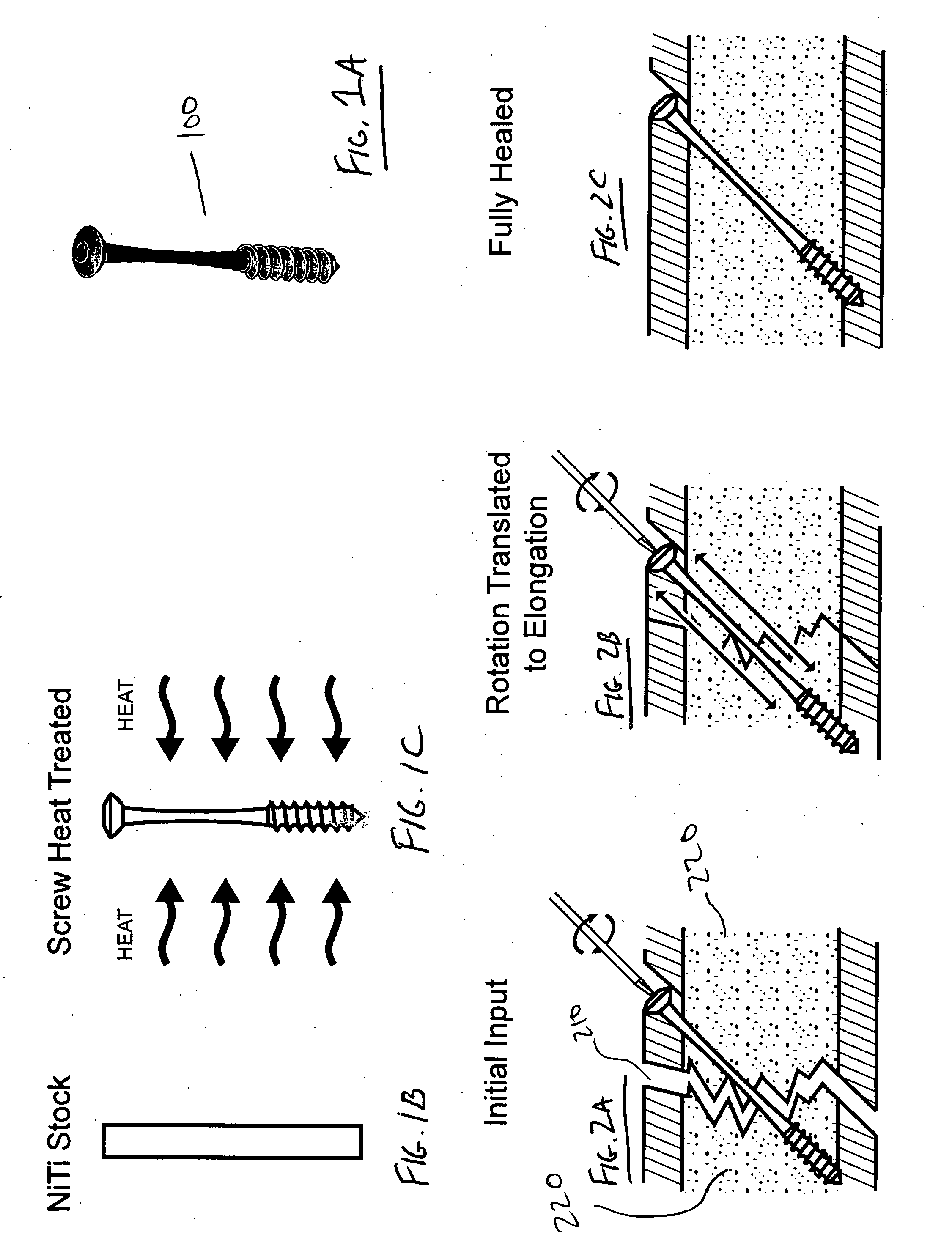
[0032] It has been determined that when a bone is set and a compressive force is applied to the fracture fixation device, the force between the fragments ends decreases rapidly as a function of time. Ideally, the fixation device is able to maintain a compressive force, which will allow for the continuation of healing through reduction of the fracture gap, and stability of the fracture gap. If this does not occur, a loss of compression may be followed by the lack of union and stability of the fracture site, which in turn reduces the healing. A fracture fixation device is put in place to stabilize the fracture site, however, if the compressive force is not present then micro-motion between the fracture ends may occur. This, in turn, may cause unnecessary resorption, which will lead to non-union of the bone or the presence of large voids. These reasons show the importance of a device to actively match the changes in the body, as well as have a similar response as bone.

[0033] Embodimen...


PUM


Abstract

The present invention provides bone fracture fixation devices, systems and methods of use and manufacture. One such bone fixation device includes an elongate element having a responsive zone. The element is adapted to be coupled to the bone so that the responsive zone is positioned adjacent a fracture site in the bone. The responsive zone is adapted to apply a desired pressure to the bone when coupled thereto. In some embodiments, the responsive zone comprises a shape memory material, which may be nickel titanium or Nitinol, to apply compressive pressure across the fracture site for longer periods of time than standard bone screws.

Description

CROSS-REFERENCES TO RELATED APPLICATIONS [0001] The present application claims priority to U.S. Provisional Application No. 60 / 563,952, filed Apr. 21, 2004, entitled Shape Memory Alloy Osteosynthetic Implants, the complete disclosure of which is incorporated herein by reference for all purposes.BACKGROUND OF THE INVENTION [0002] The present application relates generally to bone fracture repair, and more specifically, to osteosynthetic implants for fracture repair and methods of their use and manufacture. [0003] In 1959, a group of Swiss Orthopedic and General Surgeons formed the Arbeitsgemeinschaft fur Osteosynthesefragen (AO), also known as the Association for the Study of Internal Fixation (ASIF). The AO / ASIF is now a multi-national group of doctors and scientists with the expressed purpose of studying bone healing and continuous development of fracture fixation techniques for patient care. In the United States, as well as most other countries, AO / ASIF guidance regarding skeletal ...

Claims


Application Information

Patent Timeline
Patent Type & Authority Applications(United States)
IPC IPC(8): A61B17/00A61B17/56A61B17/72A61B17/80A61B17/86
CPCA61B17/62A61B17/66A61B17/7225A61B2017/00867A61B17/7291A61B17/8004A61B17/866A61B17/7283
Inventor GALL, KENNETH A.TYBER, JEFFREY A.PACACCIO, DOUGLAS J.
Owner MEDSHAPE
Why Eureka
Try Eureka