Fluid delivery system and mounting panel therefor

a technology of fluid delivery system and mounting panel, which is applied in the direction of valve housing, sustainable manufacturing/processing, transportation and packaging, etc., can solve the problems of reducing the flexibility of laying out the fluid channels, reducing the cost of manufacturing such systems, and reducing the cost of fluid delivery systems. , to achieve the effect of reducing the size of the overall fluid delivery system (which includes the mounting panel) and excellent compatibility with most fluids

Inactive Publication Date: 2005-11-03
SMC CORP
View PDF5 Cites 5 Cited by
  • Summary
  • Abstract
  • Description
  • Claims
  • Application Information

AI Technical Summary

Benefits of technology

[0012] Through conventional machining processes, the channels are carved out of the underside of the top plate and are enclosed by the bottom plate or an interior plate if one exists. In a complex fluid delivery system having many fluid channels, the mounting panel may include one or more interior panels with additional channels carved out of the interior plates to accommodate all routing paths. By carving channels into plates, the size and the cost of fabricating a mounting panel is significantly reduced. Moreover, it increases the flexibility in selecting a routing path for the channels, enabling one mounting panel to include channels running in two or more directions (e.g., the x and y directions in the case where only the top plate includes channels and in the x, y, and z directions where an interior plate also includes channels). The fact that channels can run in two or more directions enables two or more gas / fluid sticks to be connected and mounted on one mounting panel. In addition, the channels can be curved which provides more flexibility in designing the mounting panel and allows for a more efficient layout of the channels than might otherwise be possible using only straight-line channels.
[0014] In one embodiment, the plates of the mounting panel are attached using a polymeric compound, such as benzocyclobutene (BCB). BCB demonstrates excellent compatibility with most fluids in the semiconductor industry. This novel use of BCB to attach plates in a mounting panel is more cost effective than conventional means for attaching components in a mounting panel.

Problems solved by technology

A significant cost of the fluid delivery system is the cost of the manifold or mounting panel on which the individual control and sensing components are mounted.
Moreover, in the system of the '355 patent, the fluid channels, which are built by connecting multiple mounting blocks, run only in two straight-line directions, which limits the flexibility in laying out the fluid channels.
Because of such limited flexibility and the number of mounting blocks required, the size of fluid delivery system in the '355 patent is typically quite large, rendering the cost of manufacturing such system expensive.
Also, the large physical size prevents locating the fluid delivery system in close proximity to the reaction chamber to which it is supplying fluids.
This results in slower response times for switching gases and in other deleterious effects associated with large dead volumes, not the least of which is a decrease in productivity.
Furthermore, the flow channels in each mounting block run in only one direction, which means that connecting multiple gas sticks together appears to require additional mounting blocks with channels running in substantially perpendicular directions to those of each gas stick.
Therefore, although mounting blocks of the '177 patent may provide some advantages over those described in the '355 patent, they still have many of the same size and cost disadvantages.
A cost-effective solution analogous to the electrical delivery system has not been applied to gas panels or fluid delivery panels because of material and manufacturing limitations.
Specifically, the low levels of contamination mandated by high purity processes, such as those encountered in the semiconductor, pharmaceutical, or optical fiber industry, severely restrict the materials which can be employed as well as the fabrication techniques (for example, welding panel components together often introduces sites for corrosion or particle generation).

Method used


Image

  • Fluid delivery system and mounting panel therefor
  • Fluid delivery system and mounting panel therefor
  • Fluid delivery system and mounting panel therefor

Examples


Embodiment Construction

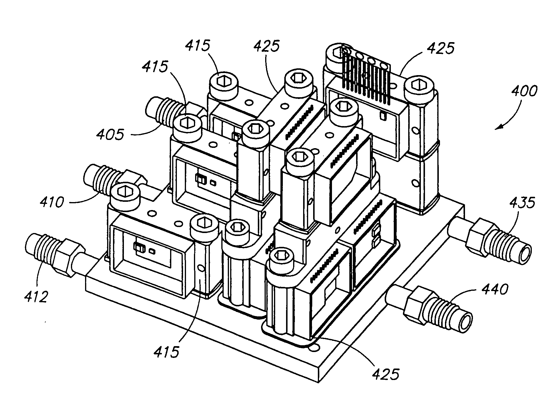
[0026] Similar to an electric circuit, a fluid delivery system can be represented by a schematic diagram, an example of which is illustrated in FIG. 3. The example schematic illustrates how fluids, such as liquids or gases, entering the fluid delivery system through input lines 305, 310, and 312 are routed through flow-control devices 315, 325 to output and vacuum lines 340 and 335, respectively. In this example, flow-control devices 315 and 325 are shut-off valves and combined shut-off valves / mass flow controller devices, respectively. The lines connecting the input points 305, 310, 312 to the output and vacuum lines 340, 335 represent the routing paths or “channels” through which the fluids are routed.

[0027] A fluid delivery system of the present invention includes flow-control devices mounted on a mounting panel. The type, number, and configuration of such flow-control devices will vary depending on the fluid flow requirements of each application. The fluid delivery system of th...


PUM


Abstract

A novel fluid delivery system includes a mounting panel, where the mounting panel includes channels that define the flow of fluid between any flow-control components mounted on the mounting panel. The mounting panel comprises a top plate and a bottom plate, and the channels are carved out of the underside of the top plate and are enclosed by the bottom plate. In a complex fluid delivery system having many fluid channels, the mounting panel may include one or more interior panels with additional channels carved out of the interior plates to accommodate all routing paths. The channels run in two or more directions to connect two or more gas / channel sticks together.

Description

RELATED APPLICATIONS [0001] This application is a continuation of U.S. Patent Application No. 10 / 377,831, filed on Mar. 3, 2003, and titled “Fluid Delivery and Mounting Panel Therefor,” the contents of which are incorporated by reference as if fully disclosed herein.FIELD OF THE INVENTION [0002] The present inventions relates generally to gas panels and fluid delivery systems, and more specifically to a mounting panel in a fluid delivery system. DESCRIPTION OF THE BACKGROUND ART [0003] High purity gas delivery systems, like those used in semiconductor manufacturing or other tightly controlled processes, typically use a source of high purity gas that is distributed and controlled through a series of gas distribution and control components, such as a mass flow controller, one or more pressure sensors and / or regulators, one or more filters or purifiers, and shutoff valves. In semiconductor processing, a series-connected set of such components is usually referred to as a “gas stick” or ...

Claims


Application Information

Patent Timeline
Patent Type & Authority Applications(United States)
IPC IPC(8): F15B13/08F16K27/00
CPCF15B13/081F15B13/0814F15B13/0857F16K27/003F15B13/0892F15B13/0896F15B13/0871Y10T137/87885Y02P80/10
Inventor HARRIS, JAMES M.MICHAEL, SELSER J.
Owner SMC CORP
Why Eureka
Try Eureka