Liquid crystal display device, display device and backlight device

a display device and liquid crystal technology, applied in lighting and heating apparatus, identification means, instruments, etc., can solve the problems of large backlight portion weight and other problems, and achieve the effect of extending the optical path length, and reducing the weight of the backlight portion

Inactive Publication Date: 2005-11-03
PANASONIC LIQUID CRYSTAL DISPLAY CO LTD
View PDF2 Cites 66 Cited by
  • Summary
  • Abstract
  • Description
  • Claims
  • Application Information

AI Technical Summary

Benefits of technology

[0021] According to the backlight device of the invention, it is possible to ensure the long effective optical path length by reducing the thickness of the direct backlight portion of the solid-state light emitting element and hence, it is possible to obtain the light-source light having the high brightness uniformity and the high chromaticity uniformity whereby the brightness / power consumption ratio can be enhanced thus giving rise to extremely excellent advantageous effects such as the reduction of the number and the quantity of solid-state light emitting elements and the optical parts.
[0022] Further, according to the backlight device of the invention, by using a light transmitting liquid as a material of the sub light guide body, it is possible to reduce the weight of the backlight portion. Further, by dividing the sub light guide body into a plurality of sub light guide bodies with at least one layer of air layer therebetween, the weight of the backlight portion can be further reduced and, at the same time, the optical path length can be elongated. Further, with the use of the side emitter type solid-state light emitting element, it is possible to obtain extremely excellent advantageous effects such as the further enhancement of the light utilizing efficiency, the high brightness and the like.
[0023] Further, according to the backlight device of the invention, it is possible to acquire extremely excellent advantageous effects including the realization of the solid-state light-emitting-element direct backlight for a large-sized display device which can, compared to the cold cathode fluorescent lamp which uses mercury, obtain a light-source light which exhibits the substantially equal or higher brightness uniformity and the substantially equal or higher chromaticity uniformity and uses no mercury to satisfy the demand for the preservation of environment.
[0024] According to another aspect of the invention, in a liquid crystal display device which includes a liquid crystal display panel which is constituted by sandwiching a liquid crystal layer between a pair of transparent substrates having electrodes for forming pixels on inner surfaces thereof and a backlight device which is mounted on a back surface of the liquid crystal display panel, the backlight device includes a main light guide body which has a light irradiation surface which irradiates light forwardly by developing the light in plane, a sub light guide body which is arranged on a back surface of the main light guide body, is divided into a first sub light guide body and a second sub light guide body on both end sides by way of a first air layer disposed in the vicinity of a center portion, and forms light incident surfaces on facing end surfaces of the first sub light guide body and the second sub light guide body in the inside of the first air layer, reflectors which are arranged on both end surfaces of the main light guide body and the sub light guide body and optically couple the main light guide body and the sub light guide body, and a solid-state light emitting element board which is mounted in a state that solid-state light emitting elements capable of emitting light of respective colors consisting of R, G, B in the inside of the first air layer of the sub light guide body are arranged at least in a row.
[0025] The solid-state light emitting element is preferably a side-emitter-type solid-state light emitting element.
[0026] Further, the backlight device may be configured such that the main light guide body has a light reflection surface which faces the light irradiation surface in an opposed manner and reflects the light toward the light irradiation surface, and the sub light guide body includes a first light reflection surface on a surface thereof which faces the main light guide body and a second light reflection surface on a back surface which faces the first light reflection surface in an opposed manner.

Problems solved by technology

That is, it is necessary to form a gap having the large thickness and hence, a thickness of the backlight portion is formed largely correspondingly thus giving rise to a drawback that a shape or the like of the backlight portion becomes also large.

Method used


Image

  • Liquid crystal display device, display device and backlight device
  • Liquid crystal display device, display device and backlight device
  • Liquid crystal display device, display device and backlight device

Examples


embodiment 1

[Embodiment 1]

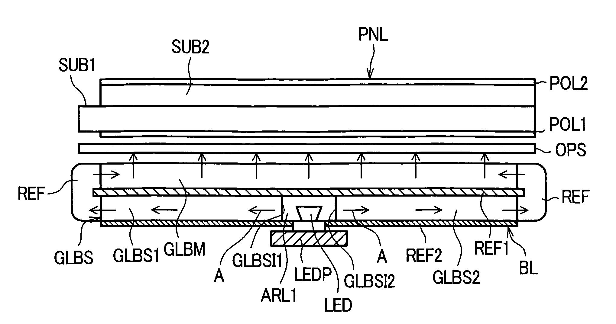
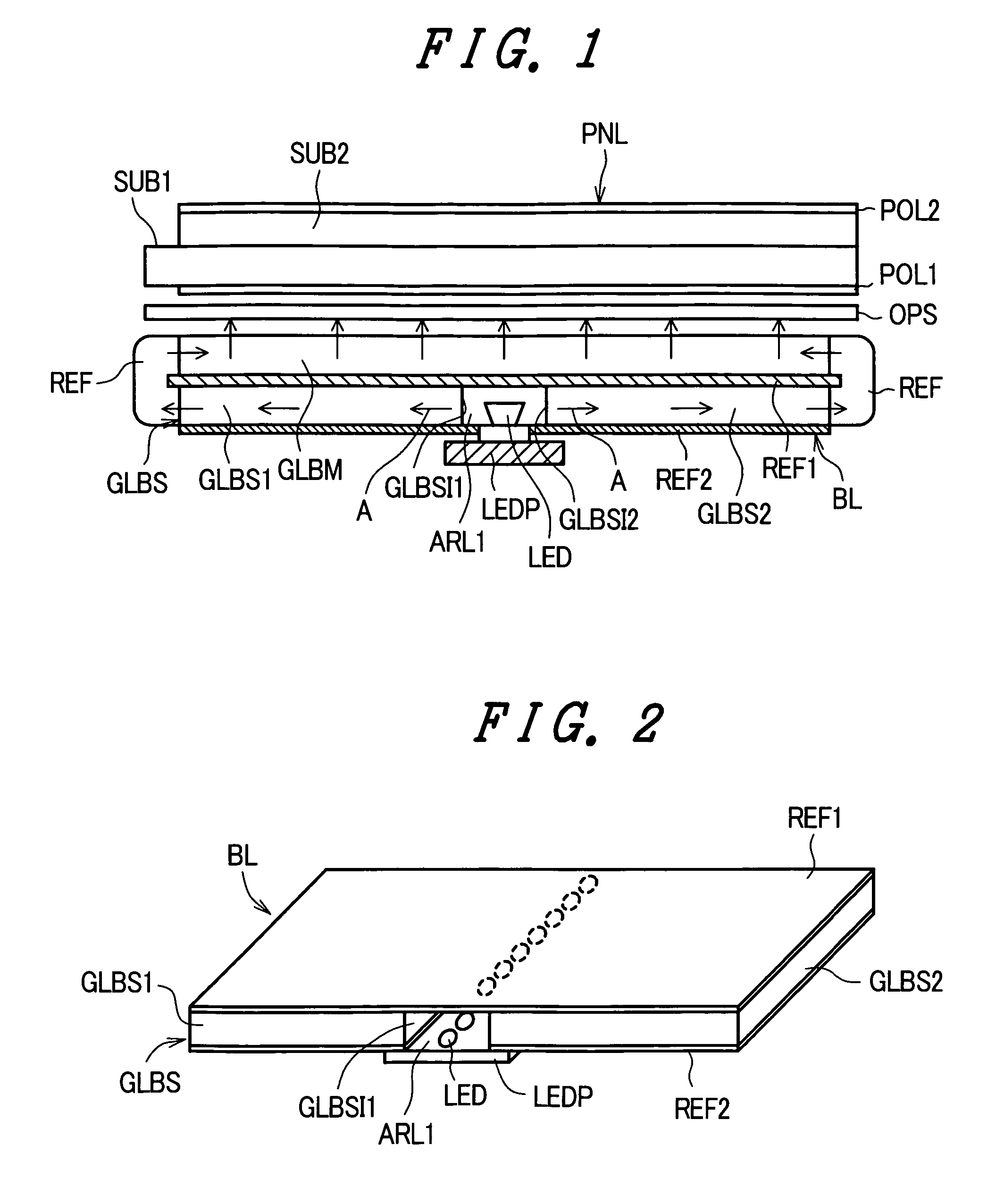
[0063]FIG. 1 is a cross-sectional view of an essential part for explaining the constitution according to an embodiment 1 of a backlight device of the invention and a liquid crystal display device which constitutes a display device having the backlight device. In FIG. 1, reference symbol PNL indicates a liquid crystal display panel which constitutes a display panel. The liquid crystal display panel PNL sandwiches a liquid crystal layer between a first substrate SUB1 and a second substrate SUB2. The liquid crystal display panel PNL also includes electrodes, active elements or the like for forming pixels on an inner surface or inner surfaces of either one or both of glass-made first substrate SUB1 and / or second substrate SUB2. Here, the first substrate SUB1 on which the active elements such as thin film transistors (TFT) are formed is also referred to as an active matrix substrate and the first substrate SUB1 which uses the thin film transistors is also referred to as a T...

embodiment 2

[Embodiment 2]

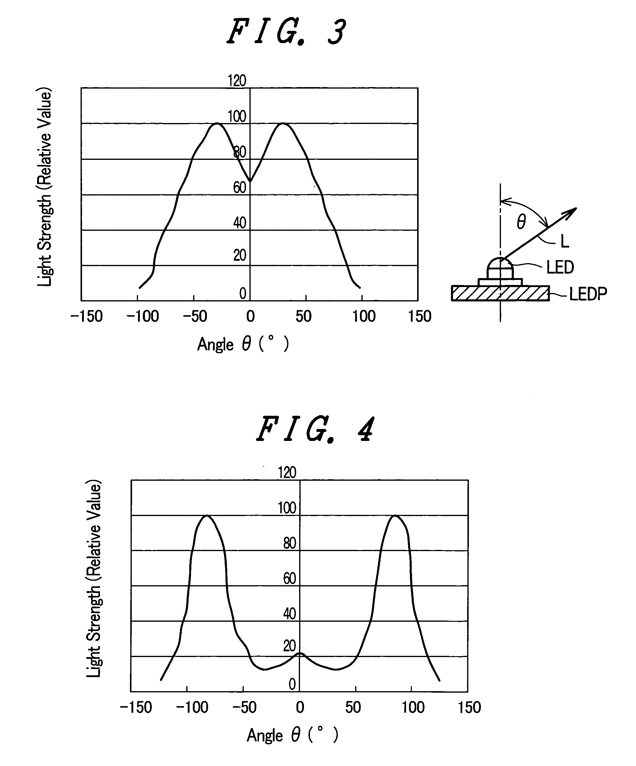
[0075] The shape of the respective light incident surfaces GLBS11 and light incident surfaces GLBS12 of the sub light guide plate GLBS (the first sub light guide plate GLBS1 and the second sub light guide plate GLBS2) which allows the incidence of the irradiated light from the light emitting diodes LED (the light emitting diodes LED1 and the light emitting diodes LED2) is an important factor which has an influence in determining an optical path length of the light which propagates in the inside of the sub light guide plate GLBS. Assuming that the LED inclination angle θ is approximately 80° and a half value width which halves the luminous intensity is approximately ±20° at a center portion of the light radiation pattern of the light emitting diode LED, to set the incident angle of the light beams at the center portion to 0°, that is, to prevent the light beams from refraction on an air layer-light guide plate boundary face, as shown in FIG. 9 which is an enlarged cross...

embodiment 3

[Embodiment 3]

[0078] Currently, the main light guide plate and the sub light guide plates are manufactured using a light transmitting resin material such as an acrylic resin material or a polycarbonate-orientated material and the densities of these light transmitting resin materials are approximately 1.10 g / cm3. In a commercially available 20-inch-class liquid crystal television set which uses a cold cathode fluorescent lamp as a light source, only one main light guide plate is used. However, the weight of the main light guide plate is extremely heavy, that is, approximately 1 Kg or more. In the liquid crystal television of the same class which uses light emitting diodes capable of emitting lights of three colors consisting of R (red), G (green), B (blue) as a light source, the total weight of the main light guide plate and the sub light guide plates becomes approximately 2 Kg.

[0079] In view of the above, as a means for reducing the weight of the light guide plate GLBS, this embodi...


PUM

PropertyMeasurementUnit
inclination angleaaaaaaaaaa
incident angleaaaaaaaaaa

Abstract

The present invention provides a backlight device which uses solid-state light emitting elements capable of emitting lights of three colors consisting of red, green and blue as a light source, can enhance the light utilizing efficiency, and can be made light-weighted. Further, the invention provides a display device which exhibits the high brightness uniformity and the high chromaticity uniformity. The backlight device includes a main light guide plate which has a light irradiation surface which irradiates light forwardly by developing the light in plane and has a light reflection surface which faces the light irradiation surface in an opposed manner and reflects the light toward the light irradiation surface; a sub light guide plate which is arranged on a back surface of the main light guide plate, is divided into a first sub light guide plate and a second sub light guide plate on both end sides by way of a first air layer disposed at a center portion, and forms light incident surfaces on facing end surfaces of the first sub light guide plate and the second sub light guide plate in the inside of the first air layer; a first light reflection plate which is arranged on a front surface of the sub light guide plate which faces the main light guide plate; a second light reflection plate which is arranged on a back surface of the sub light guide plate which faces the first light reflection plate in an opposed manner; reflectors which are arranged on both end surfaces of the main light guide plate and the sub light guide plate and optically couple the main light guide plate and the sub light guide plate; and a light emitting diode board which is mounted in a state that the light emitting diode board faces a back surface of the sub light guide plate and light emitting diodes capable of emitting light of plurality of colors in the inside of the first air layer are arranged at least in a row. Due to such a constitution, a light-source light from the light emitting diodes capable of emitting lights of plurality of colors is subjected to color mixture and an effective optical path can be elongated and hence, the light utilizing efficiency can be enhanced and, at the same time, the backlight device can be made light-weighted.

Description

CROSS-REFERENCE TO RELATED APPLICATIONS [0001] The disclosure of Japanese Patent Application No. 2004-127662 filed on Apr. 23, 2004 including the specification, drawings and abstract is incorporated herein by reference in its entirety. BACKGROUND OF THE INVENTION [0002] The present invention relates to a liquid crystal display device, a display device, and a backlight device, and more particularly to a solid-state-light-emitting-element (LED) direct backlight device which is mounted on a back surface side of a display device and irradiates a light-source light to the display device and the display device which uses the backlight device. [0003] Recently, as a backlight used in a large-sized liquid crystal television set, a large-sized monitor or the like, a cold cathode fluorescent lamp has been mainly popularly used. The backlight device which uses the cold cathode fluorescent lamp is roughly classified into a side-edge type backlight device which arranges a cold cathode fluorescent...

Claims


Application Information

Patent Timeline
Patent Type & Authority Applications(United States)
IPC IPC(8): G02B6/00F21V8/00F21Y101/02G02F1/1335G02F1/13357G09F9/00
CPCG02B6/0018G02B6/0021G02B6/0028G02F1/133603G02B6/0068G02B6/0073G02B6/0055
Inventor KOGANEZAWA, NOBUYUKI
Owner PANASONIC LIQUID CRYSTAL DISPLAY CO LTD
Why Eureka
Try Eureka