Overlay device and computer tomography device comprising an emitter side overlay device

a technology of overlay device and overlay device, which is applied in the direction of instruments, radiation diagnostic diaphragms, and diaphragms used in diaphragms/collimeters, etc., can solve the problems of unfavorable radiation exposure, unnecessarily increasing radiation exposure, and only unnecessarily affecting patient radiation exposure, etc., and achieves a small space requirement and less expenditure

Active Publication Date: 2005-11-03
SIEMENS HEALTHCARE GMBH
View PDF2 Cites 11 Cited by
  • Summary
  • Abstract
  • Description
  • Claims
  • Application Information

AI Technical Summary

Benefits of technology

[0010] An object of the present invention is to provide a gating device which can be produced with less expenditure, which exhibits a small space requirement and which nevertheless allows a gating adapted to the geometry of an, if applicable, associated x-ray detector. A computed tomography apparatus should also be specified for this purpose.

Problems solved by technology

Other x-rays would only unnecessarily penetrate the patient and unnecessarily increase the radiation exposure.
Given conventional flat or planar diaphragm plates or absorber elements, this is not perfectly possible due to different separations of the x-rays of the ray beam, respectively measured from the focus of the x-ray radiator to the point of impact on the diaphragm plate.
This at best possible with very large mechanical effort.
Moreover, the production of a support body curved around two axes is likewise connected with large expenditure, because this must also still be produced from x-ray-absorbing material, meaning from a material with a high atomic number.
A further disadvantage of the x-ray collimator known from U.S. Pat. No. 6,396,902 is its large structural volume.

Method used


Image

  • Overlay device and computer tomography device comprising an emitter side overlay device
  • Overlay device and computer tomography device comprising an emitter side overlay device
  • Overlay device and computer tomography device comprising an emitter side overlay device

Examples


Embodiment Construction

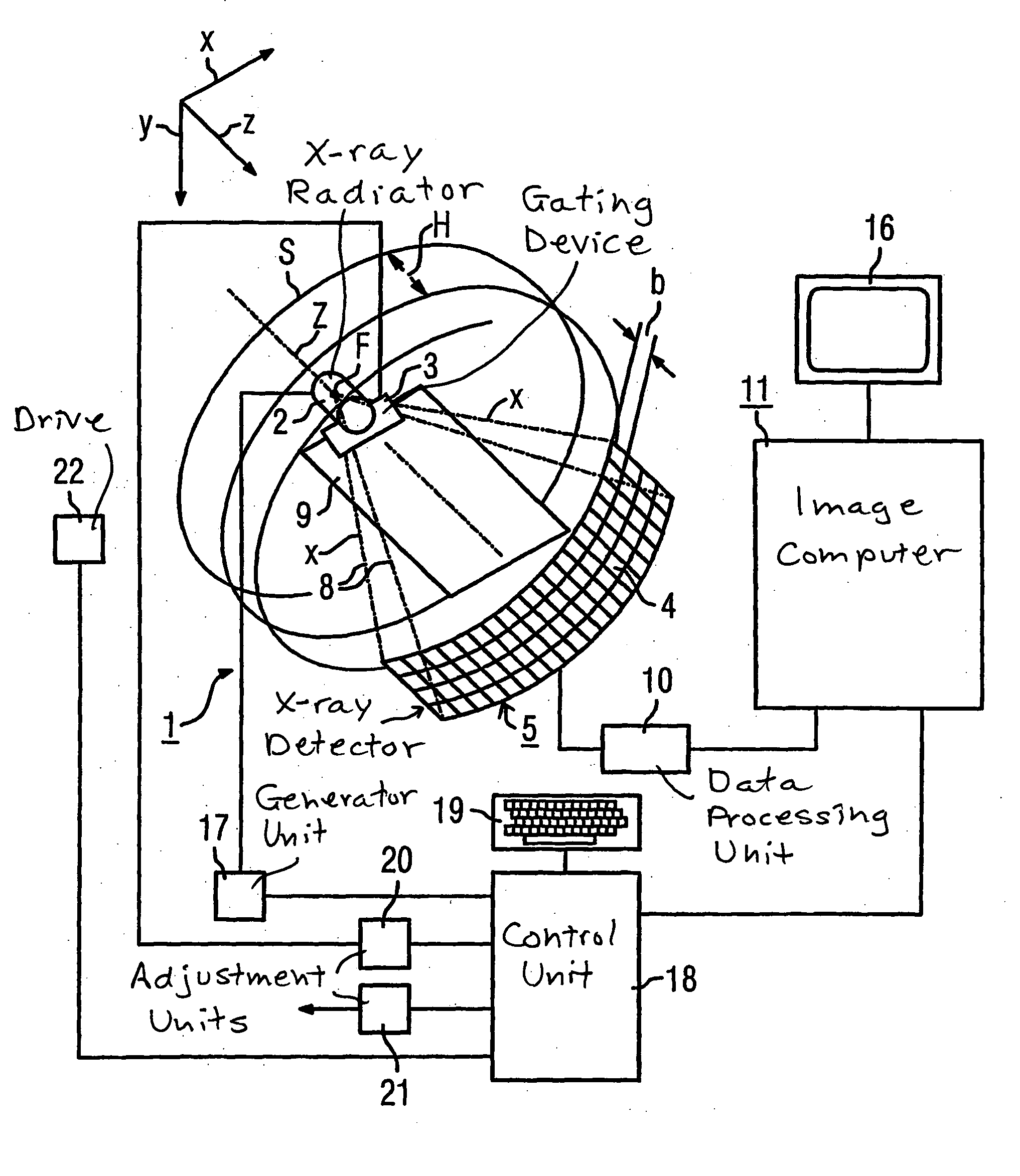
[0035] A CT apparatus of the generation is shown in FIG. 1 in section. Its measurement arrangement includes an x-ray radiator 2 with a gating device 3 positioned in front of it, near the source, and an x-ray detector 5, fashioned as a laminar array of a number of rows and columns of detector elements (one of these is designated with 4 in FIG. 1), with an optional beam diaphragm (not shown) positioned in front of the x-ray detector 5, close to the detector. For clarity, in FIG. 1 only four rows of detector elements 4 are shown; however, the x-ray detector 5 can have further rows of detector elements 4, optionally with different widths b.

[0036] The x-ray radiator 2 with the gating device 3 on one side and the x-ray detector 5 with its beam diaphragm on the other side are mounted opposite one another on a rotary frame (gantry) (not shown), such that a pyramidal (viewed in the z-direction: fan-shaped) x-ray beam, emitted by the x-ray radiator 2 in the operation of the CT apparatus 1 an...


PUM


Abstract

A gating device to delimit an x-ray beam, said gating device comprising a device housing, first and second absorber elements mounted in said device housing opposite each other, an adjustment device connected to said first and second absorber elements for moving said absorber elements relative to each other to set a spacing between said first and second absorber elements forming a slit for passage of an x-ray beam therethrough, each of said absorber elements having an absorber element edge shaped to give said slit a slit width that varies in a longitudinal direction of the slit, said slit width increasing outwardly, from a central position, toward respectively opposite ends of said slit, each slit edge, in said longitudinal direction of said slit, having a middle region producing a uniform width of said slit and, further regions respectively disposed on opposite sides of said middle region that produce a linearly increasing slit width in said longitudinal direction of said slit, and said adjustment device producing a parallelogram-like relative movement between said absorber elements.

Description

BACKGROUND OF THE INVENTION [0001] 1. Field of the Invention [0002] The invention concerns a gating device to delimit an x-ray beam, of the type having two absorber elements disposed opposite one another that are adjustable with an adjustment device as to their distance from one another, via which a slit for passage of the x-ray beam can be delimited, wherein the absorber elements are shaped such that the slit exhibits a slit width varying in the slit longitudinal direction, the slit width increasing toward both slit ends starting from a middle position. The invention also concerns a computed tomography apparatus with an x-ray radiator rotatable around a system axis, with an x-ray detector and with a radiator-side gating device. [0003] 2. Description of the Prior Art [0004] In an examination of an examination subject or a patient in an x-ray diagnostic apparatus, the examination subject is moved into an x-ray beam emitted by an x-ray source, and the radiation attenuation resulting f...

Claims


Application Information

Patent Timeline
Patent Type & Authority Applications(United States)
IPC IPC(8): A61B6/06G21K1/02G21K1/04
CPCA61B6/06G21K1/04G21K1/025
Inventor DISTLER, FRIEDRICHPAULI, KARLHEINZWALLSCHLAGER, HEINRICH
Owner SIEMENS HEALTHCARE GMBH
Why Eureka
Try Eureka